ST90158 - TIMER/WATCHDOG (WDT)
TIMER/WATCHDOG (Cont’d)
9.1.5 Register Description
TIMER/WATCHDOG PRESCALER REGISTER
(WDTPR)
R250 - Read/Write
Register Page: 0
Reset value: 1111 1111 (FFh)
The Timer/Watchdog is associated with 4 registers
mapped into Group F, Page 0 of the Register File.
WDTHR: Timer/Watchdog High Register
WDTLR: Timer/Watchdog Low Register
WDTPR: Timer/Watchdog Prescaler Register
WDTCR: Timer/Watchdog Control Register
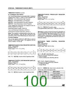
7
0
PR7 PR6 PR5 PR4 PR3 PR2 PR1 PR0
Three additional control bits are mapped in the fol-
lowing registers on Page 0:
Bits 7:0 = PR[7:0] Prescaler value.
A programmable value from 1 (00h) to 256 (FFh).
Watchdog Mode Enable, (WCR.6)
Top Level Interrupt Selection, (EIVR.2)
Interrupt A0 Channel Selection, (EIVR.1)
Warning: In order to prevent incorrect operation of
the Timer/Watchdog, the prescaler (WDTPR) and
counter (WDTRL, WDTRH) registers must be ini-
tialised before starting the Timer/Watchdog. If this
is not done, counting will start with the reset (un-in-
itialised) values.
Note: The registers containing these bits also con-
tain other functions. Only the bits relevant to the
operation of the Timer/Watchdog are shown here.
Counter Register
This 16-bit register (WDTLR, WDTHR) is used to
load the 16-bit counter value. The registers can be
read or written “on the fly”.
WATCHDOG TIMER CONTROL REGISTER
(WDTCR)
R251- Read/Write
Register Page: 0
Reset value: 0001 0010 (12h)
TIMER/WATCHDOG HIGH REGISTER (WDTHR)
R248 - Read/Write
Register Page: 0
Reset value: 1111 1111 (FFh)
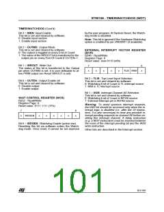
7
0
ST_SP S_C INMD1 INMD2 INEN OUTMD WROUT OUTEN
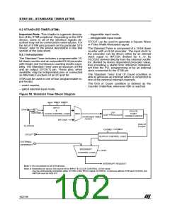
7
0
R15 R14 R13 R12 R11 R10
R9
R8
Bit 7 = ST_SP: Start/Stop Bit.
This bit is set and cleared by software.
0: Stop counting
Bits 7:0 = R[15:8] Counter Most Significant Bits.
1: Start counting (see Warning above)
TIMER/WATCHDOG LOW REGISTER (WDTLR)
R249 - Read/Write
Register Page: 0
Bit 6 = S_C: Single/Continuous.
This bit is set and cleared by software.
0: Continuous Mode
Reset value: 1111 1111b (FFh)
1: Single Mode
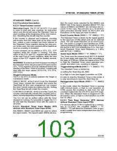
7
0
Bits 5:4 = INMD[1:2]: Input mode selection bits.
R7
R6
R5
R4
R3
R2
R1
R0
These bits select the input mode:
INMD1
INMD2
INPUT MODE
Event Counter
Bits 7:0 = R[7:0] Counter Least Significant Bits.
0
0
1
1
0
1
0
1
Gated Input (Reset value)
Triggerable Input
Retriggerable Input
100/199
9

 ETC [ ETC ]