ST90158 - TIMER/WATCHDOG (WDT)
TIMER/WATCHDOG (Cont’d)
Bit 3 = INEN: Input Enable.
This bit is set and cleared by software.
0: Disable input section
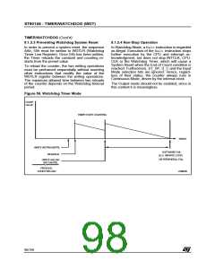
by the user program. At System Reset, the Watch-
dog mode is disabled.
Note: This bit is ignored if the Hardware Watchdog
option is enabled by pin HW0SW1 (if available).
1: Enable input section
Bit 2 = OUTMD: Output Mode.
This bit is set and cleared by software.
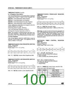
EXTERNAL INTERRUPT VECTOR REGISTER
(EIVR)
R246 - Read/Write
0: The output is toggled at every End of Count
1: The value of the WROUT bit is transferred to the
output pin on every End Of Count if OUTEN=1.
Register Page: 0
Reset value: xxxx 0110 (x6h)
Bit 1 = WROUT: Write Out.
7
x
0
x
The status of this bit is transferred to the Output
pin when OUTMD is set; it is user definable to al-
low PWM output (on Reset WROUT is set).
x
x
x
x
TLIS IA0S
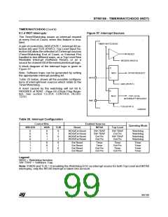
Bit 2 = TLIS: Top Level Input Selection.
This bit is set and cleared by software.
0: Watchdog End of Count is TL interrupt source
1: NMI is TL interrupt source
Bit 0 = OUTEN: Output Enable bit.
This bit is set and cleared by software.
0: Disable output
1: Enable output
Bit 1 = IA0S: Interrupt Channel A0 Selection.
This bit is set and cleared by software.
0: Watchdog End of Count is INTA0 source
1: External Interrupt pin is INTA0 source
WAIT CONTROL REGISTER (WCR)
R252 - Read/Write
Register Page: 0
Warning: To avoid spurious interrupt requests,
the IA0S bit should be accessed only when the in-
terrupt logic is disabled (i.e. after the DI instruc-
tion). It is also necessary to clear any possible in-
terrupt pending requests on channel A0 before en-
abling this interrupt channel. A delay instruction
(e.g. a NOP instruction) must be inserted between
the reset of the interrupt pending bit and the IA0S
write instruction.
Reset value: 0111 1111 (7Fh)
7
x
0
x
WDGEN
x
x
x
x
x
Bit 6 = WDGEN: Watchdog Enable (active low).
Resetting this bit via software enters the Watch-
dog mode. Once reset, it cannot be set anymore
Other bits are described in the Interrupt section.
101/199
9

 ETC [ ETC ]