ST90158 - STANDARD TIMER (STIM)
STANDARD TIMER (Cont’d)
9.2.5 Register Description
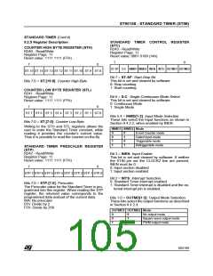
STANDARD TIMER CONTROL REGISTER
(STC)
R243 - Read/Write
Register Page: 11
Reset value: 0001 0100 (14h)
COUNTER HIGH BYTE REGISTER (STH)
R240 - Read/Write
Register Page: 11
Reset value: 1111 1111 (FFh)
7
0
7
0
ST-SP S-C INMD1 INMD2 INEN INTS OUTMD1 OUTMD2
ST.15 ST.14 ST.13 ST.12 ST.11 ST.10 ST.9 ST.8
Bit 7 = ST-SP: Start-Stop Bit.
This bit is set and cleared by software.
0: Stop counting
Bits 7:0 = ST.[15:8]: Counter High-Byte.
1: Start counting
COUNTER LOW BYTE REGISTER (STL)
R241 - Read/Write
Bit 6 = S-C: Single-Continuous Mode Select.
This bit is set and cleared by software.
0: Continuous Mode
Register Page: 11
Reset value: 1111 1111 (FFh)
7
0
1: Single Mode
ST.7 ST.6 ST.5 ST.4 ST.3 ST.2 ST.1 ST.0
Bits 5:4 = INMD[1:2]: Input Mode Selection.
These bits select the Input functions as shown in
Section 9.4.2.2, when enabled by INEN.
Bits 7:0 = ST.[7:0]: Counter Low Byte.
Writing to the STH and STL registers allows the
user to enter the Standard Timer constant, while
reading it provides the counter’s current value.
Thus it is possible to read the counter on-the-fly.
INMD1 INMD2 Mode
0
0
1
1
0
1
0
1
Event Counter mode
Gated input mode
Triggerable mode
Retriggerable mode
STANDARD TIMER PRESCALER REGISTER
(STP)
R242 - Read/Write
Register Page: 11
Reset value: 1111 1111 (FFh)
Bit 3 = INEN: Input Enable.
This bit is set and cleared by software. If neither
the STIN pin nor the CLOCK2 line are present,
INEN must be 0.
7
0
0: Input section disabled
1: Input section enabled
STP.7 STP.6 STP.5 STP.4 STP.3 STP.2 STP.1 STP.0
Bit 2 = INTS: Interrupt Selection.
0: Standard Timer interrupt enabled
1: Standard Timer interrupt is disabled and the ex-
ternal interrupt pin is enabled.
Bits 7:0 = STP.[7:0]: Prescaler.
The Prescaler value for the Standard Timer is pro-
grammed into this register. When reading the STP
register, the returned value corresponds to the
programmed data instead of the current data.
00h: No prescaler
01h: Divide by 2
FFh: Divide by 256
Bits 1:0 = OUTMD[1:2]: Output Mode Selection.
These bits select the output functions as described
in Section 9.4.2.4.
OUTMD1 OUTMD2 Mode
0
0
1
0
1
x
No output mode
Square wave output mode
PWM output mode
105/199
9

 ETC [ ETC ]