ST72104G, ST72215G, ST72216G, ST72254G
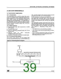
WATCHDOG TIMER (Cont’d)
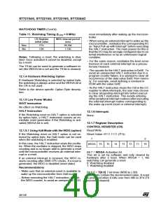
Table 11. Watchdog Timing (f
= 8 MHz)
reset immediately after waking up the microcon-
troller.
CPU
CR Register
initial value
WDG timeout period
(ms)
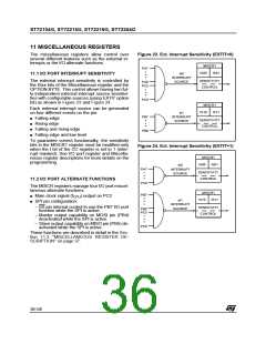
– When using an external interrupt to wake up the
microcontroller, reinitialize the corresponding I/O
as “Input Pull-up with Interrupt” before executing
the HALT instruction. The main reason for this is
that the I/O may be wrongly configured due to ex-
ternal interference or by an unforeseen logical
condition.
Max
Min
FFh
C0h
98.304
1.536
Notes: Following a reset, the watchdog is disa-
bled. Once activated it cannot be disabled, except
by a reset.
– For the same reason, reinitialize the level sensi-
tiveness of each external interrupt as a precau-
tionary measure.
The T6 bit can be used to generate a software re-
set (the WDGA bit is set and the T6 bit is cleared).
– The opcode for the HALT instruction is 0x8E. To
avoid an unexpected HALT instruction due to a
program counter failure, it is advised to clear all
occurrences of the data value 0x8E from memo-
ry. For example, avoid defining a constant in
ROM with the value 0x8E.
12.1.4 Hardware Watchdog Option
If Hardware Watchdog is selected by option byte,
the watchdog is always active and the WDGA bit in
the CR is not used.
– As the HALT instruction clears the I bit in the CC
register to allow interrupts, the user may choose
to clear all pending interrupt bits before execut-
ing the HALT instruction. This avoids entering
other peripheral interrupt routines after executing
the external interrupt routine corresponding to
the wake-up event (reset or external interrupt).
Refer to the device-specific Option Byte descrip-
tion.
12.1.5 Low Power Modes
WAIT Instruction
No effect on Watchdog.
HALT Instruction
12.1.6 Interrupts
If the Watchdog reset on HALT option is selected
by option byte, a HALT instruction causes an im-
mediate reset generation if the Watchdog is acti-
vated (WDGA bit is set).
None.
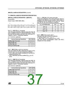
12.1.7 Register Description
CONTROL REGISTER (CR)
Read/Write
12.1.5.1 Using Halt Mode with the WDG (option)
If the Watchdog reset on HALT option is not se-
lected by option byte, the Halt mode can be used
when the watchdog is enabled.
Reset Value: 0111 1111 (7Fh)
7
0
In this case, the HALT instruction stops the oscilla-
tor. When the oscillator is stopped, the WDG stops
counting and is no longer able to generate a reset
until the microcontroller receives an external inter-
rupt or a reset.
WDGA T6
T5
T4
T3
T2
T1
T0
Bit 7 = WDGA Activation bit.
This bit is set by software and only cleared by
hardware after a reset. When WDGA = 1, the
watchdog can generate a reset.
0: Watchdog disabled
1: Watchdog enabled
If an external interrupt is received, the WDG re-
starts counting after 4096 CPU clocks. If a reset is
generated, the WDG is disabled (reset state).
Recommendations
– Make sure that an external event is available to
wake up the microcontroller from Halt mode.
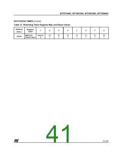
Bit 6:0 = T[6:0] 7-bit timer (MSB to LSB).
These bits contain the decremented value. A reset
is produced when it rolls over from 40h to 3Fh (T6
becomes cleared).
– Before executing the HALT instruction, refresh
the WDG counter, to avoid an unexpected WDG
40/140

 ETC [ ETC ]