ST72104G, ST72215G, ST72216G, ST72254G
12 ON-CHIP PERIPHERALS
12.1 WATCHDOG TIMER (WDG)
12.1.1 Introduction
cles, and the length of the timeout period can be
programmed by the user in 64 increments.
The Watchdog timer is used to detect the occur-
rence of a software fault, usually generated by ex-
ternal interference or by unforeseen logical condi-
tions, which causes the application program to
abandon its normal sequence. The Watchdog cir-
cuit generates an MCU reset on expiry of a pro-
grammed time period, unless the program refresh-
es the counter’s contents before the T6 bit be-
comes cleared.
If the watchdog is activated (the WDGA bit is set)
and when the 7-bit timer (bits T6:T0) rolls over
from 40h to 3Fh (T6 becomes cleared), it initiates
a reset cycle pulling low the reset pin for typically
500ns.
The application program must write in the CR reg-
ister at regular intervals during normal operation to
prevent an MCU reset. The value to be stored in
the CR register must be between FFh and C0h
(see Table 11 . Watchdog Timing (fCPU = 8
MHz)):
12.1.2 Main Features
■ Programmable timer (64 increments of 12288
CPU cycles)
– The WDGA bit is set (watchdog enabled)
■ Programmable reset
– The T6 bit is set to prevent generating an imme-
diate reset
■ Reset (if watchdog activated) when the T6 bit
reaches zero
■ Optional
reset
on
HALT
instruction
– The T5:T0 bits contain the number of increments
which represents the time delay before the
watchdog produces a reset.
(configurable by option byte)
■ Hardware Watchdog selectable by option byte.
12.1.3 Functional Description
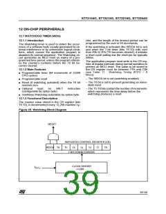
The counter value stored in the CR register (bits
T6:T0), is decremented every 12,288 machine cy-
Figure 25. Watchdog Block Diagram
RESET
WATCHDOG CONTROL REGISTER (CR)
T5 T0
WDGA T6
T1
T4
T2
T3
7-BIT DOWNCOUNTER
CLOCK DIVIDER
f
CPU
÷12288
39/140

 ETC [ ETC ]