ST6200C/ST6201C/ST6203C
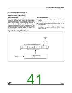
WATCHDOG TIMER (Cont’d)
9.1.7 Register Description
WATCHDOG REGISTER (WDGR)
Address: 0D8h - Read/Write
Reset Value: 1111 1110 (FEh)
When C is kept cleared the counter can be used
as a 7-bit timer.
0: Watchdog deactivated
1: Watchdog activated
Bit 1 = SR: Software Reset bit
7
0
Software can generate a reset by clearing this bit
while the C bit is set. When C = 0 (Watchdog de-
activated) the SR bit is the MSB of the 7-bit timer.
0: Generate (write)
T0
T1
T2
T3
T4
T5
SR
C
Bit 0= C Watchdog Control bit.
1: No software reset generated, MSB of 7-bit timer
If the hardware option is selected (WDACT bit in
Option byte), this bit is forced high and cannot be
changed by the user (the Watchdog is always ac-
tive). When the software option is selected
(WDACT bit in Option byte), the Watchdog func-
tion is activated by setting the C bit, and cannot
then be deactivated (except by resetting the
MCU).
Bit 5:0 = T[5:0] Downcounter bits
Caution: These bits are reversed and shifted with
respect to the physical counter: bit-7 (T0) is the
LSB of the Watchdog downcounter and bit-2 (T5)
is the MSB.
44/104
1

 ETC [ ETC ]