ST6200C/ST6201C/ST6203C
7.2 WAIT MODE
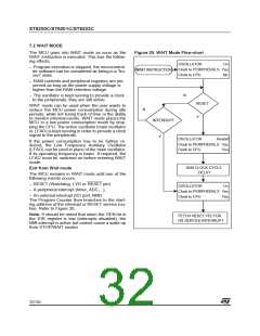
The MCU goes into WAIT mode as soon as the
WAIT instruction is executed. This has the follow-
ing effects:
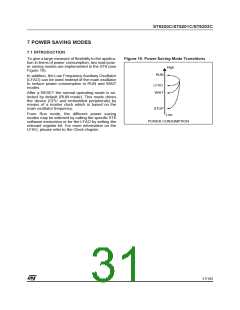
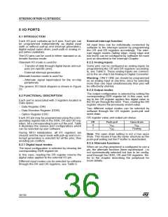
Figure 20. WAIT Mode Flow-chart
OSCILLATOR
On
– Program execution is stopped, the microcontrol-
ler software can be considered as being in a “fro-
zen” state.
Clock to PERIPHERALS Yes
WAIT INSTRUCTION
Clock to CPU
No
– RAM contents and peripheral registers are pre-
served as long as the power supply voltage is
higher than the RAM retention voltage.
N
– The oscillator is kept running to provide a clock
to the peripherals; they are still active.
RESET
WAIT mode can be used when the user wants to
reduce the MCU power consumption during idle
periods, while not losing track of time or the ability
to monitor external events. WAIT mode places the
MCU in a low power consumption mode by stop-
ping the CPU. The active oscillator (main oscillator
or LFAO) is kept running in order to provide a clock
signal to the peripherals.
N
Y
INTERRUPT
Y
OSCILLATOR
Restart
If the power consumption has to be further re-
duced, the Low Frequency Auxiliary Oscillator
(LFAO) can be used in place of the main oscillator,
if its operating frequency is lower. If required, the
LFAO must be switched on before entering WAIT
mode.
Clock to PERIPHERALS Yes
Clock to CPU Yes
2048 CLOCK CYCLE
DELAY
Exit from Wait mode
The MCU remains in WAIT mode until one of the
following events occurs:
– RESET (Watchdog, LVD or RESET pin)
– A peripheral interrupt (timer, ADC,...),
OSCILLATOR
On
Clock to PERIPHERALS Yes
– An external interrupt (I/O port, NMI)
The Program Counter then branches to the start-
ing address of the interrupt or RESET service rou-
tine. Refer to Figure 20.
Clock to CPU
Yes
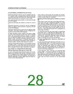
Note: It should be noted that when the GEN bit in
the IOR register is low (interrupts disabled), the
NMI interrupt is active but cannot cause a wake up
from STOP/WAIT modes.
FETCH RESET VECTOR
OR SERVICE INTERRUPT
32/104
1

 ETC [ ETC ]