ST6200C/ST6201C/ST6203C
CPU REGISTERS (Cont’d)
The 12-bit length allows the direct addressing of
4096 bytes in Program Space.
Z : Zero flag
This flag is set if the result of the last arithmetic or
logical operation was equal to zero; otherwise it is
cleared.
However, if the program space contains more than
4096 bytes, the additional memory in program
space can be addressed by using the Program
ROM Page register.
0: The result of the last operation is different from
zero
1: The result of the last operation is zero
The PC value is incremented after reading the ad-
dress of the current instruction. To execute relative
jumps, the PC and the offset are shifted through
the ALU, where they are added; the result is then
shifted back into the PC. The program counter can
be changed in the following ways:
Switching between the three sets of flags is per-
formed automatically when an NMI, an interrupt or
a RETI instruction occurs. As NMI mode is auto-
matically selected after the reset of the MCU, the
ST6 core uses the NMI flags first.
– JP (Jump) instruction
– CALL instruction
PC = Jump address
PC = Call address
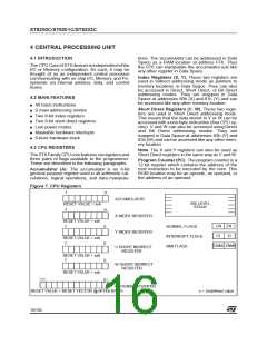
Stack. The ST6 CPU includes a true LIFO (Last In
First Out) hardware stack which eliminates the
need for a stack pointer. The stack consists of six
separate 12-bit RAM locations that do not belong
to the data space RAM area. When a subroutine
call (or interrupt request) occurs, the contents of
each level are shifted into the next level down,
while the content of the PC is shifted into the first
level (the original contents of the sixth stack level
are lost). When a subroutine or interrupt return oc-
curs (RET or RETI instructions), the first level reg-
ister is shifted back into the PC and the value of
each level is popped back into the previous level.
– Relative Branch InstructionPC = PC +/- offset
– Interrupt
– Reset
PC = Interrupt vector
PC = Reset vector
– RET & RETI instructions PC = Pop (stack)
– Normal instruction PC = PC + 1
Flags (C, Z). The ST6 CPU includes three pairs of
flags (Carry and Zero), each pair being associated
with one of the three normal modes of operation:
Normal mode, Interrupt mode and Non Maskable
Interrupt mode. Each pair consists of a CARRY
flag and a ZERO flag. One pair (CN, ZN) is used
during Normal operation, another pair is used dur-
ing Interrupt mode (CI, ZI), and a third pair is used
in the Non Maskable Interrupt mode (CNMI, ZN-
MI).
Figure 8. Stack manipulation
PROGRAM
COUNTER
The ST6 CPU uses the pair of flags associated
with the current mode: as soon as an interrupt (or
a Non Maskable Interrupt) is generated, the ST6
CPU uses the Interrupt flags (or the NMI flags) in-
stead of the Normal flags. When the RETI instruc-
tion is executed, the previously used set of flags is
restored. It should be noted that each flag set can
only be addressed in its own context (Non Maska-
ble Interrupt, Normal Interrupt or Main routine).
The flags are not cleared during context switching
and thus retain their status.
ON RETURN
FROM
ON
INTERRUPT,
OR
SUBROUTINE
CALL
LEVEL 1
LEVEL 2
LEVEL 3
LEVEL 4
LEVEL 5
LEVEL 6
INTERRUPT,
OR
SUBROUTINE
Since the accumulator, in common with all other
data space registers, is not stored in this stack,
management of these registers should be per-
formed within the subroutine.
C : Carry flag.
This bit is set when a carry or a borrow occurs dur-
ing arithmetic operations; otherwise it is cleared.
The Carry flag is also set to the value of the bit
tested in a bit test instruction; it also participates in
the rotate left instruction.
0: No carry has occured
1: A carry has occured
Caution: The stack will remain in its “deepest” po-
sition if more than 6 nested calls or interrupts are
executed, and consequently the last return ad-
dress will be lost.
It will also remain in its highest position if the stack
is empty and a RET or RETI is executed. In this
case the next instruction will be executed.
17/104
1

 ETC [ ETC ]