ST6200C/ST6201C/ST6203C
3.3 OPTION BYTES
Each device is available for production in user pro-
grammable versions (OTP) as well as in factory
coded versions (ROM). OTP devices are shipped
to customers with a default content (00h), while
ROM factory coded parts contain the code sup-
plied by the customer. This implies that OTP de-
vices have to be configured by the customer using
the Option Bytes while the ROM devices are facto-
ry-configured.
LSB OPTION BYTE
Bit 7 = PROTECT Readout Protection.
This option bit enables or disables external access
to the internal program memory.
0: Program memory not read-out protected
1: Program memory read-out protected
Bit 6 = OSC Oscillator selection.
This option bit selects the main oscillator type.
0: Quartz crystal, ceramic resonator or external
clock
The two option bytes allow the hardware configu-
ration of the microcontroller to be selected.
The option bytes have no address in the memory
map and can be accessed only in programming
mode (for example using a standard ST6 program-
ming tool).
In masked ROM devices, the option bytes are
fixed in hardware by the ROM code (see Section
12.6.2 ”ROM VERSION” on page 97).
1: RC network
Bit 5 = Reserved, must be always cleared.
Bit 4 = Reserved, must be always set.
The option bytes can be only programmed once. It
is not possible to change the selected options after
they have been programmed.
Bit 3 = NMI PULL NMI Pull-Up on/off.
This option bit enables or disables the internal pull-
up on the NMI pin.
0: Pull-up disabled
1: Pull-up enabled
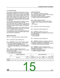
MSB OPTION BYTE
Bit 15:11 = Reserved, must be always cleared.
Bit 2 = Reserved, must be always set.
Bit 10 = Reserved, must be always set.
Bit 1 = WDACT Hardware or software watchdog.
This option bit selects the watchdog type.
0: Software (watchdog to be enabled by software)
1: Hardware (watchdog always enabled)
Bit 9 = EXTCNTL External STOP MODE control.
0: EXTCNTL mode not available. STOP mode is
not available with the watchdog active.
1: EXTCNTL mode available. STOP mode is avail-
able with the watchdog active by setting NMI pin
to one.
Bit 0 = OSGEN Oscillator Safeguard on/off.
This option bit enables or disables the oscillator
Safeguard (OSG) feature.
0: Oscillator Safeguard disabled
1: Oscillator Safeguard enabled
Bit 8 = LVD Low Voltage Detector on/off.
This option bit enable or disable the Low Voltage
Detector (LVD) feature.
0: Low Voltage Detector disabled
1: Low Voltage Detector enabled.
MSB OPTION BYTE
LSB OPTION BYTE
15
8
7
0
EXT
PRO-
TECT
NMI
PULL
WD OSG
Reserved
CTL
LVD
OSC Res. Res.
Res.
X
ACT
EN
Default
Value
X
X
X
X
X
X
X
X
X
X
X
X
X
X
X
15/104
1

 ETC [ ETC ]