ST6200C/ST6201C/ST6203C
3.2 PROGRAMMING MODES
3.2.1 Program Memory
Note: OTP/EPROM devices can be programmed
with the development tools available from
STMicroelectronics (please refer to Section 13 on
page 99).
Table 3. EPROM/OTP programming mode issetby
a +12.5V voltage applied to the TEST/V pin. The
PP
programming flowofthe ST62T00C, T01/E01Cand
T03C is described in the User Manual of the
EPROM Programming Board.
3.2.2 EPROM Erasing
The EPROM devices can be erased by exposure
to Ultra Violet light. The characteristics of the MCU
are such that erasure begins when the memory is
exposed to light with a wave lengths shorter than
approximately 4000Å. It should be noted that sun-
light and some types of fluorescent lamps have
wavelengths in the range 3000-4000Å.
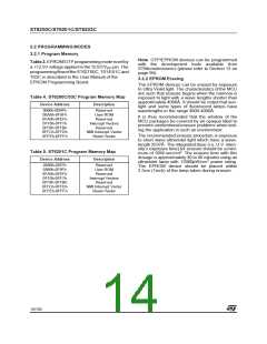
Table 4. ST6200C/03C Program Memory Map
Device Address
Description
0000h-0B9Fh
0BA0h-0F9Fh
0FA0h-0FEFh
0FF0h-0FF7h
0FF8h-0FFBh
0FFCh-0FFDh
0FFEh-0FFFh
Reserved
User ROM
Reserved
It is thus recommended that the window of the
MCU packages be covered by an opaque label to
prevent unintentional erasure problems when test-
ing the application in such an environment.
Interrupt Vectors
Reserved
NMI Interrupt Vector
Reset Vector
The recommended erasure procedure is exposure
to short wave ultraviolet light which have a wave-
length 2537Å. The integrated dose (i.e. U.V. inten-
sity x exposure time) for erasure should be a mini-
Table 5. ST6201C Program Memory Map
2
mum of 30W-sec/cm . The erasure time with this
dosage is approximately 30 to 40 minutes using an
ultraviolet lamp with 12000µW/cm power rating.
The EPROM device should be placed within
2.5cm (1inch) of the lamp tubes during erasure.
Device Address
Description
2
0000h-087Fh
0880h-0F9Fh
0FA0h-0FEFh
0FF0h-0FF7h
0FF8h-0FFBh
0FFCh-0FFDh
0FFEh-0FFFh
Reserved
User ROM
Reserved
Interrupt Vectors
Reserved
NMI Interrupt Vector
Reset Vector
14/104
1

 ETC [ ETC ]