RTL8211C & RTL8211CL
Datasheet
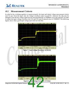
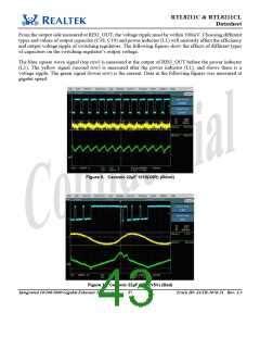
From the output side measured at REG_OUT, the voltage ripple must be within 100mV. Choosing different
types and values of output capacitor (C18, C19) and power inductor (L1) will seriously affect the efficiency
and output voltage ripple of switching regulators. The following figures show the effects of different types
of capacitors on the switching regulator’s output voltage.
The blue square wave signal (top row) is measured at the output of REG_OUT before the power inductor
(L1). The yellow signal (second row) is measured after the power inductor (L1), and shows there is a
voltage ripple. The green signal (lower row) is the current. Data in the following figures was measured at
gigabit speed.
Figure 9. Ceramic 22µF 1210(X5R) (Good)
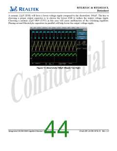
Figure 10. Ceramic 22µF 0805(Y5V) (Bad)
Integrated 10/100/1000 Gigabit Ethernet Transceiver 37
Track ID: JATR-1076-21 Rev. 1.3

 ETC [ ETC ]