RTL8211C & RTL8211CL
Datasheet
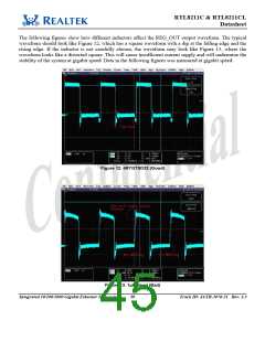
The following figures show how different inductors affect the REG_OUT output waveform. The typical
waveform should look like Figure 12, which has a square waveform with a dip at the falling edge and the
rising edge. If the inductor is not carefully chosen, the waveform may look like Figure 13, where the
waveform looks like a distorted square. This will cause insufficient current supply and will undermine the
stability of the system at gigabit speed. Data in the following figures was measured at gigabit speed.
Figure 12. 4R7GTSD32 (Good)
Figure 13. 1µH Bead (Bad)
Integrated 10/100/1000 Gigabit Ethernet Transceiver 39
Track ID: JATR-1076-21 Rev. 1.3

 ETC [ ETC ]