RTL8211C & RTL8211CL
Datasheet
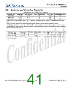
8.2. Inductor and Capacitor Parts List
Table 40. Inductor and Capacitor Parts List
Inductor Type
4R7GTSD32
6R8GTSD32
6R8GTSD53
Inductance
5.1µH
Q at 500KHz
57.15
ESR at 500KHz (MΩ)
Max I (mA) Output Ripple (mV)
281
313
375
1100
900
12.6
12
6.7µH
67.35
7.1µH
59.7
1510
10.4
Note 1: The ESR is equivalent to RDC or DCR. Lower ESR inductor values will promote a higher efficiency switching
regulator.
Note 2: The power inductor used by the switching regulator should be able to withstand 600mA of current.
Note 3: Typically, if the power inductor’s ESR at 1MHz is below 0.8Ω, the switching regulator efficiency will be above
75%. However the actual switching regulator efficiency must be measured according to the method described in section 8.5
Efficiency Measurement, page 41.
Capacitor Type
22µF 1210 TDK
22µF 1210 X5R
Capacitance
21.5µF
ESR at 500KHz (MΩ)
Output Ripple (mV) Load Transient (mV)
24.25
24.90
9.6
81.0
73.0
22.15µF
10.4
Note: Capacitors (C18 and C82) are suggested to be ceramic due to their low ESR value. Lower ESR values will yield lower
output voltage ripple.
Integrated 10/100/1000 Gigabit Ethernet Transceiver
35
Track ID: JATR-1076-21 Rev. 1.3

 ETC [ ETC ]