5
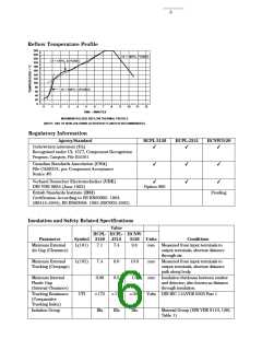
Reflow Temperature Profile
260
240
220
∆T = 145°C, 1°C/SEC
∆T = 115°C, 0.3°C/SEC
200
180
160
140
120
100
80
∆T = 100°C, 1.5°C/SEC
60
40
20
0
0
1
2
3
4
5
6
7
8
9
10
11
12
TIME – MINUTES
MAXIMUM SOLDER REFLOW THERMAL PROFILE
(NOTE: USE OF NON-CHLORINE ACTIVATED FLUXES IS RECOMMENDED.)
Regulatory Information
Agency/Standard
HCPL-3120
HCPL-J312
HCNW3120
Underwriters Laboratory (UL)
✔
✔
✔
Recognized under UL 1577, Component Recognition
Program, Category, File E55361
Canadian Standards Association (CSA)
File CA88324, per Component Acceptance
Notice #5
✔
✔
✔
✔
Verband Deutscher Electrotechniker (VDE)
✔
✔
DIN VDE 0884 (June 1992)
Option 060
British Standards Institute (BSI)
Pending
Certification According to BS EN60065: 1994
(BS415:1994), BS EN60950: 1992 (BS7002:1992)
Insulation and Safety Related Specifications
Value
HCPL- HCPL- HCNW
Parameter
Symbol 3120
J312
3120
Units
Conditions
Minimum External
Air Gap (Clearance)
L(101)
7.1
7.4
9.6
mm
mm
mm
Measured from input terminals to
output terminals, shortest distance
through air.
Measured from input terminals to
output terminals, shortest distance
path along body.
Insulation thickness between emitter
and detector; also known as distance
through insulation.
Minimum External
Tracking (Creepage)
L(102)
7.4
8.0
0.5
10.0
1.0
Minimum Internal
Plastic Gap
(Internal Clearance)
0.08
Tracking Resistance
(Comparative
Tracking Index)
CTI
>175 >175
>200
IIIa
Volts DIN IEC 112/VDE 0303 Part 1
Isolation Group
IIIa
IIIa
Material Group (DIN VDE 0110, 1/89,
Table 1)

 ETC [ ETC ]