VT82885
Real Time Clock
VIA Technologies, Inc.
lected using the same Register A bits which
selected the square wave frequency (see
Table 1). Changing the Register A bits af-
fects both the square wave frequency and
the periodic interrupt output. However, each
function has a separate enable bit in Regis-
ter B. The SQWE bit controls the square
wave output. Similarly the periodic interrupt
is enabled by the PIE bit in Register B. The
periodic interrupt can be used with software
counters to measure inputs, create output
intervals, or await the next needed software
function.
possibility of accessing inconsistent time and
calendar data. The first method uses the
update-ended interrupt. If enabled, an
interrupt occurs after every up date cycle
that indicates that over 999 ms are available
to read valid time and date information. If
this interrupt is used, the IRQF bit in Regis-
ter C should be cleared before leaving the
interrupt routine.
A second method uses the update-in-
progress bit (UIP) in Register A to determine
if the update cycle is in progress. The UIP bit
will pulse once per second. After the UIP bit
UPDATE CYCLE
µs
goes high, the update transfer occurs 244
later. If a low is read on the UIP bit, the user
has at least 244 µsbefore the time/calendar
data will be changed. There-fore, the user
should avoid interrupt service routines that
would cause the time needed to read valid
time/calendar data to exceed 244 µs.
The VT82885 executes an update cycle
once per second regardless of the SET bit in
Register B. When the SET bit in Register B
is set to one, the user copy of the double
buffered time, calendar and alarm bytes is
frozen and will not update as the time in-
crements. However, the time countdown
chain continues to update the internal copy
of the buffer. This feature allows time to
maintain accuracy independent of reading or
writing the time, calendar and alarm buf-fers
and also guarantees that time and cal-endar
information is consistent. The update cycle
also compares each alarm byte with the
corresponding time byte and issues an
alarm if a match or if a “don’t care” code is
present in all three positions.
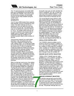
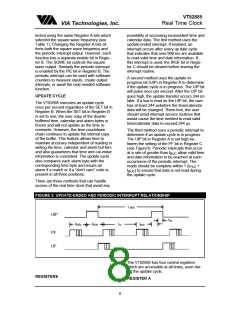
The third method uses a periodic interrupt to
determine if an update cycle is in progress.
The UIP bit in Register A is set high be-
tween the setting of the PF bit in Register C
(see Figure3). Periodic interrupts that occur
at a rate of greater than t
allow valid time
BUC
and date information to be reached at each
occurrence of the periodic interrupt. The
reads should be complete within 1 (t
+
P1/2
t ) to ensure that data is not read during
BUC
the update cycle.
There are three methods that can handle
access of the real time clock that avoid any
FIGURE 3: UPDATE-ENDED AND PERIODIC INTERRUPT RELATIONSHIP
1 sec
UIP
tUC
(tPI)/2
(tPI)/2
tPI
tBUC
PF
UF
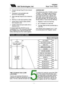
The VT82885 has four control registers
which are accessible at all times, even dur-
ing the update cycle.
REGISTERS
REGISTER A
8

 ETC [ ETC ]