VT82885
Real Time Clock
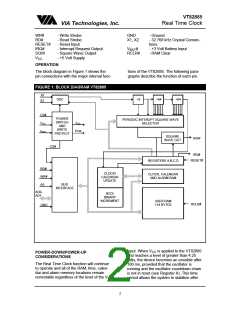
VIA Technologies, Inc.
should be written to a logic one to prevent
updates from occurring while access is be-
ing attempted. In addition to writing the ten
time, calendar and alarm registers in a se-
lected format (binary or BCD), the data
mode bit (DM) of Register B must be set to
the appropriate logic level. All ten time, cal-
endar and alarm bytes must use the same
data mode. The set bit in Register B should
be cleared after the data mode bit has been
written to allow the real time clock to update
the time and calendar bytes. Once initial-
ized, the real time clock makes all updates in
the selected mode. The data mode can-not
be changed without reinitializing the ten data
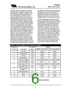
bytes. Table 2 shows the binary and BCD
formats of the ten time, calendar and alarm
locations. The 24-12 bit cannot be changed
without reinitializing the hour loca-tions.
When the 12-hour format is selected, the
high order bit of the hours byte repre-sents
PM when it is a logic one. Once per second
the ten bytes are advanced by one second
and checked for an alarm condition. If a read
of the time and calendar data oc-curs during
an update, a problem exists where seconds,
minutes, hours, etc. may not correlate. The
probability of reading in-correct time and
calendar data is low. Sev-eral methods of
avoiding any possible incor-rect time and
calendar reads are covered later in this text.
The three alarm bytes can be used in two
ways. First, when the alarm time is written in
the appropriate hours, minutes and seconds
alarm locations, the alarm interrupt is initi-
ated at the specified time each day if the
alarm enable bit is high. The second use
condition is to insert a “don’t care” state in
one or more of the three alarm bytes. The
“don’t care” code is any hexadecimal value
from C0 to FF. The two most significant bits
of each byte set the “don’t care” condition
when at logic 1. An alarm will be generated
each hour when the “don’t care” bits are set
in the hours byte. Similarily, an alarm is
generated every minute with “don’t care”
codes in the hours and minute alarm bytes.
The “don’t care” codes in all three alarm
bytes create an interrupt every second.
TABLE 2: TIME. CALENDAR AND ALARM DATA MODES
ADDRESS
DECIMAL
RANGE
0-59
RANGE
BINARY DATA MODE
LOCATION
FUNCTION
Seconds
BCD DATA MODE
00-59
0
1
2
3
4
00-3B
00-3B
Seconds Alarm
Minutes
0-59
00-59
0-59
00-3B
00-59
Minutes Alarm
Hours-12-hr Mode
Hours-24-hr Mode
Hours Alarm-12-hr
Hours Alarm-24-hr
0-59
00-3B
00-59
1.12
01-0C AM, 81-8C PM
00-17
01-12AM,81-92PM
00-23
0-23
5
6
1-12
01-0C AM, 81-8C PM
00-17
01-12AM,81-92PM
00-23
0-23
Day of the Week
Sunday = 1
1-7
01-07
01-07
7
8
9
Date of the Month
Month
1-31
1-12
0-99
01-1F
01-0C
00-63
01-31
01-12
00-99
Year
NONVOLATILE RAM
6

 ETC [ ETC ]