iW1688
Low-Power Off-line Digital PWM Controller
9.8 CCM Protection
The iW1688 has a built-in protection circuit which detects if
the combination of the on-time and reset time exceed 25ms
(the total period of the typical 40kHz operating frequency). If
it is allowed to occur, the system would go into Continuous
Conduction Mode (CCM), which could saturate the
transformer and lead to damage of the power MOSFET. If
the system tries to go into CCM mode, the iW1688 will send
100ns minimum on-time with a 100ns delay.
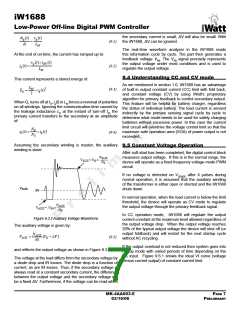
9.6 Constant Current Operation
The iW1688 has been designed to work in constant-current
mode for battery charging applications. If the output voltage
drops, but does not go below 20% of the nominal designed
value, the device operates in this mode.
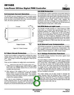
±10%
9.9 PFM Mode at Light Load
CV mode
V
±5%
NOM
The iW1688 normally operates in a fixed frequency PWM
mode when IOUT is greater than approximately 10% of the
specified maximum load current. As the output load IOUT is
reduced, the on-time tON is decreased. At the moment that
the load current drops below 10% of nominal, the controller
transitions to Pulse Frequency Modulation (PFM) mode.
Thereafter, the on-time will be modulated by the line voltage
and the off-time is modulated by the load current. The device
automatically returns to PWM mode when the load current
increases
20% of
V
NOM
130% of
I
9.10 Internal Loop Compensation
Output Current
NOM
The iW1688 incorporates an internal Digital Error Amplifier
with no requirement for external loop compensation. The
loop stability is guaranteed by design to provide at least 45
degrees of phase margin and –20dB of gain margin.
Figure 9.6.1 Power Envelope
9.7 Short Circuit Protection
9.11 Voltage Protection Functions
A short circuit condition is interpreted as any time the output
voltage drops to less than 20% of the nominal designed
value. This change is detected typically within 150μs by the
VSENSE signal.
The iW1688 includes functions that protect against input
and output overvoltage.
The input voltage is monitored by the VIN pin and the output
voltage is monitored by the VSENSE pin. If the voltage at these
pins exceed their undervoltage or overvoltage thresholds
for more than 4-8 cycles, the iW1688 will stop switching.
However, the IC will remain biased which will discharge the
VCC supply. Once VCC drops below the UVLO threshold, the
controller will reset itself and then initiate a new soft-start
cycle. The controller will continue to attempt to soft-start until
the error condition is removed.
There are two conditions for output short-circuit detection:
1) VSENSE detects the rise of the DC supply output. If VSENSE
is less than 0.3V (typical) within 25ms of the first output
driver pulse, the controller detects this as a short circuit
condition and shuts down.
2) After start-up, if the voltage at the VSENSE pin remains
below 200mV for 6 consecutive cycles, the controller
detects a fault condition and shuts down. This condition
could occur when the output is shorted, or when there is
a fault in the auxiliary winding.
The output voltage can be high enough to damage the
output capacitor when the feedback loop is broken. The
iW1688 uses the primary feedback only with no secondary
feedback loop. When the VSENSE pin is shorted to GND (by
shorting/open sense resistor). The controller will shut off with
6 consecutive pulses after start-up.
Note: Due to some limitations of constant current mode
(CCM) protection there are some trade-offs between size
and cost of transformer, switching FET, and fixed switching
frequency for normal and abnormal (short circuit) operation.
MK-4AA003-E
03/16/06
PAGE 8
PRELIMINARY

 ETC [ ETC ]