iW1688
Low-Power Off-line Digital PWM Controller
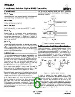
the secondary current is small, ΔV will also be small. With
the iW1688, ΔV can be ignored.
dig (t) vg (t)
=
(9.1)
dt
LM
The real-time waveform analyzer in the iW1688 reads
this information cycle by cycle. The part then generates a
feedback voltage VFB. The VFB signal precisely represents
the output voltage under most conditions and is used to
regulate the output voltage.
At the end of on-time, the current has ramped up to:
vg (t)×tON (t)
ig (t) =
(9.2)
(9.3)
LM
9.4 Understanding CC and CV mode
This current represents a stored energy of:
As we mentioned in section 1.0, iW1688 has an advantage
of built-in output constant current (CC) limit with fold back,
and constant voltage (CV) by using iWatt’s proprietary
algorithm for primary feedback to control secondary output.
This feature will be helpful for battery charger, regardless
the status of individual battery. The load current is sensed
indirectly by the primary sensing signal cycle by cycle to
determine what mode needs to be used for safely charging
batteries without excessive power. In this case the current
limit circuit will overdrive the voltage control limit so that the
maximum safe operation area (SOA) of power output is not
exceeded.
LM
Eg =
×ig (t)2
2
When Q1 turns off at tO, ig(t) in LM forces a reversal of polarities
on all windings. Ignoring the communication-time caused by
the leakage inductance LK at the instant of turn-off tO, the
primary current transfers to the secondary at an amplitude
of:
NP
id (t) =
×ig (t)
(9.4)
NS
Assuming the secondary winding is master, the auxiliary
winding is slave.
9.5 Constant Voltage Operation
After soft-start has been completed, the digital control block
measures output voltage. If this is in the normal range, the
device will operate as a fixed frequency voltage-mode PWM
circuit.
N
AUX
V
= V x
O
AUX
N
S
If no voltage is detected on VSENSE after 4 pulses during
normal operation, it is assumed that the auxiliary winding
of the transformer is either open or shorted and the iW1688
shuts down.
V
AUX
0V
In normal operation, when the load current is below the limit
threshold, the device will operate as CV mode to regulate
the output voltage through the primary feedback signal.
N
AUX
V
= -V
x
AUX
IN
N
P
In CC operation mode, iW1688 will regulate the output
current constant at the maximum level allowed regardless of
the output voltage drop. When the output voltage reaches
20% of the typical output voltage the device will shut off (or
output foldback) and will restart for the next startup cycle
without AC recycling.
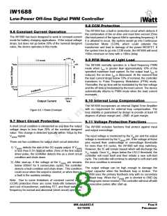
Figure 9.3.2 Auxiliary Voltage Waveforms
The auxiliary voltage is given by:
NAUX
VAUX
=
(VO + ∆V )
(9.5)
NS
If the output overload is not reduced then system goes into
hiccup mode with varied periods of time depending on the
AC input. Figure 9.6.1 shows the ideal VI curve (voltage
versus current output) of constant current limit.
and reflects the output voltage as shown in Figure 9.3.2.
The voltage at the load differs from the secondary voltage by
a diode drop and IR losses. The diode drop is a function of
current, as are IR losses. Thus, if the secondary voltage is
always read at a constant secondary current, the difference
between the output voltage and the secondary voltage will
be a fixed ΔV. Furthermore, if the voltage can be read when
MK-4AA003-E
03/16/06
PAGE 7
PRELIMINARY

 ETC [ ETC ]