iW1688
Low-Power Off-line Digital PWM Controller
The iW1688 will attempt to restart from any of these fault
conditions after VCC has discharged and then recharged to
the start-up threshold.
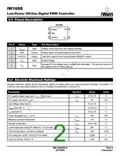
9.1 Pin Detail
Pin 1 – VSENSE
Sense signal input from auxiliary winding. This provides the
secondary voltage feedback used for output regulation.
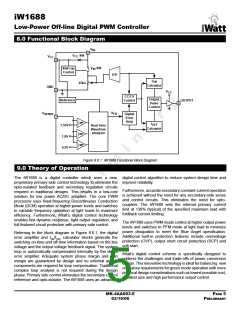
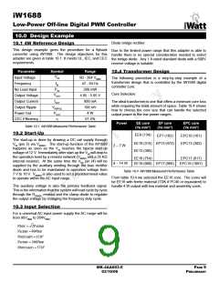
Start-up
Sequencing
Pin 2 – GND
V
IN
V
Impedance = 25k�
IN
Analog signal and power ground.
Pin 3 – OUTPUT
V
CC(ST)
Gate drive signal for the external power MOSFET switch.
Pin 4 – VCC
V
CC
OFF
ON
V
V
ON
CCSW
Power supply for the controller during normal operation.
The controller will start up when VCC reaches 12 V (typical)
and will shut-down when the VCC voltage is 6 V (typical). A
100 nF decoupling capacitor should be connected between
the VCC pin and GND.
INSW
OFF
ENABLE
200µs
Pin 5 – VIN
Figure 9.2.1 Start-up Sequencing Diagram
Sense signal input representing the average line voltage.
VIN is used for line regulation. The input line voltage is scaled
using a resistor network. It also provides input undervoltage
and overvoltage protection. This pin also provides the supply
current to the IC during start-up.
9.3 Understanding Primary Feedback
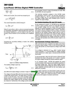
Figure 9.3.1 illustrates a simplified flyback converter. When
the switch Q1 conducts during tON(t), the current ig(t) is
directly drawn from rectified sinusoid vg(t).The energy Eg(t) is
stored in the magnetizing inductance LM. The rectifying diode
D1 is reverse biased and the load current IO is supplied by
the secondary capacitor CO. When Q1 turns off, D1 conducts
and the stored energy Eg(t) is delivered to the output.
9.2 Start-up
The iW1688 incorporates an internal soft-start function. The
soft-start time is set at 5 ms. Once the VIN pin voltage has
reached its turn-on threshold, the iW1688 starts switching,
but limits the on-time to a percentage of the maximum on-
time. During the first 1 ms, the on-time is limited to 25%.
During the next 2 ms, the on-time is limited to 50% and
during the last 2 ms, the on-time is limited to 75%.
i
(t)
i (t)
i (t)
d
in
g
N:1
V
+
O
+
D1
V
I
O
C
O
v (t)
g
v
(t)
AUX
in
–
If the output current demand is between 20% and 100% of
maximum, the iW1688 will transition from soft-start to PWM
operation. The nominal switching frequency is 40 kHz.
Q1
T (t)
S
If the power supply output current is less than 20% of nominal
after 25 ms of operation, the iW1688 assumes that the power
supply output is shorted and the device shuts down.
Figure 9.3.1 Simplified Flyback Converter
In order to regulate the output voltage within a tight
specification, the information about the output voltage and
load current needs to be accurately sensed. In the DCM
flyback converter, this information can be read via the
auxiliary winding or the primary magnetizing inductance
(LM). During the Q1 on-time, the load current is supplied from
the output filter capacitor CO. The voltage across LM is vg(t),
assuming the voltage dropped across Q1 is zero. The current
in Q1 ramps up linearly at a rate of:
If the output voltage rises above the minimum threshold
before soft-start is completed, the device assumes that
the output load is very light and immediately changes to
PFM operation. If no voltage is detected on VSENSE after 20
output pulses during start-up, it is assumed that the auxiliary
winding of the transformer is either open or shorted, and the
iW1688 shuts down.
MK-4AA003-E
03/16/06
PAGE 6
PRELIMINARY

 ETC [ ETC ]