Freescale Semiconductor, Inc.
Hardware Design
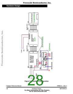
MC68HC908MR32 Control Board
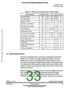
3.3 MC68HC908MR32 Control Board
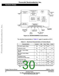
Motorola’s embedded motion control series MR32 motor control board is
designed to provide control signals for 3-phase AC induction, 3-phase
brushless DC (BLDC), and 3-phase switched reluctance (SR) motors. In
combination with one of the embedded motion control series power
stages, and an optoisolation board, it provides a software development
platform that allows algorithms to be written and tested without the need
to design and build hardware. With software supplied on the CD-ROM,
the control board supports a wide variety of algorithms for AC induction,
SR, and BLDC motors. User control inputs are accepted from
START/STOP, FWD/REV switches, and a SPEED potentiometer
located on the control board. Alternately, motor commands can be
entered via a PC and transmitted over a serial cable to DB-9 connector.
Output connections and power stage feedback signals are grouped
together on 40-pin ribbon cable connector. Motor feedback signals can
be connected to Hall sensor/encoder connector. Power is supplied
through the 40-pin ribbon cable from the optoisolation board or
low-voltage power stage.
The control board is designed to run in two configurations. It can be
connected to an M68EM08MR32 emulator via an M68CBL08A
impedance matched ribbon cable, or it can operate using the daughter
board. The M68EM08MR32 emulator board may be used in either an
MMDS05/08 or MMEVS05/08 emulation system.
Figure 3-2 shows a block diagram of the board’s circuitry.
DRM019 — Rev 0
MOTOROLA
Designer Reference Manual
Hardware Design
29
For More Information On This Product,
Go to: www.freescale.com

 ETC [ ETC ]