Data Sheet
June 1999
ORCA Series 2 FPGAs
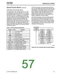
The TAPC generates control signals which allow cap-
ture, shift, and update operations on the instruction and
data registers. In the capture operation, data is loaded
into the register. In the shift operation, the captured
data is shifted out while new data is shifted in. In the
update operation, either the instruction register is
loaded for instruction decode, or the boundary-scan
register is updated for control of outputs.
Special Function Blocks (continued)
ORCA Series TAP Controller (TAPC)
The ORCA Series TAP controller (TAPC) is a 1149.1
compatible test access port controller. The 16 JTAG
state assignments from the IEEE 1149.1 specification
are used. The TAPC is controlled by TCK and TMS.
The TAPC states are used for loading the IR to allow
three basic functions in testing: providing test stimuli
(Update-DR), test execution (Run-Test/Idle), and
obtaining test responses (Capture-DR). The TAPC
allows the test host to shift in and out both instructions
and test data/results. The inputs and outputs of the
TAPC are provided in the table below. The outputs are
primarily the control signals to the instruction register
and the data register.
The test host generates a test by providing input into
the ORCA Series TMS input synchronous with TCK.
This sequences the TAPC through states in order to
perform the desired function on the instruction register
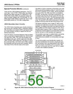
or a data register. Figure 50 provides a diagram of the
state transitions for the TAPC. The next state is deter-
mined by the TMS input value.
TEST-LOGIC-
RESET
1
Table 13. TAP Controller Input/Outputs
0
1
1
1
RUN-TEST/
IDLE
SELECT-
DR-SCAN
SELECT-
IR-SCAN
Symbol
I/O
Function
Test Mode Select
0
0
0
TMS
TCK
I
1
1
CAPTURE-DR
0
CAPTURE-IR
0
I
Test Clock
0
0
SHIFT-DR
1
SHIFT-IR
1
0
0
PUR
I
Powerup Reset
1
1
PRGM
I
BSCAN Reset
EXIT1-DR
0
EXIT1-IR
0
TRESET
Select
O
O
O
O
O
O
O
O
O
Test Logic Reset
PAUSE-DR
PAUSE-IR
Select IR (high); Select DR (low)
Test Data Out Enable
Capture/Parallel Load DR
Capture/Parallel Load IR
Shift Data Register
1
EXIT2-DR
1
1
EXIT2-IR
1
0
0
Enable
Capture-DR
Capture-IR
Shift-DR
Shift-DR
Update-DR
Update-IR
UPDATE-DR
UPDATE-IR
1
0
1
0
5-5370(F)
Shift Instruction Register
Update/Parallel Load DR
Update/Parallel Load IR
Figure 50. TAP Controller State Transition Diagram
Lucent Technologies Inc.
57

 ETC [ ETC ]