Data Sheet
June 1999
ORCA Series 2 FPGAs
I. The four TRIDIH buffers allow connections from the
pads to the PLC XH lines. The TRIDIHs also allow
connections between the PLC XH lines and the
pBIDIH lines, which are described in K below.
Programmable Input/Output Cells
(continued)
PIC Architectural Description
J. The PBIDI lines (bidi[3:0]) connect the PXL lines,
PXH lines, and the PX1 lines. These are bidirec-
tional in that the path can be from the PXL, PXH, or
PX1 lines to the XL lines, or from the XL lines to the
PXL, PXH, or PX1 lines.
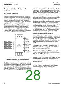
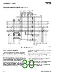
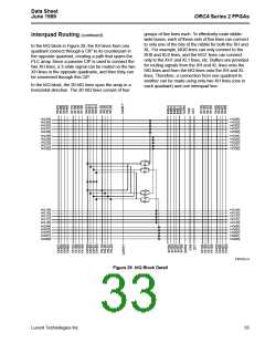
The PIC architecture given in Figure 26 is described
using the following letter references. The figure depicts
a PIC at the top of the array, so inter-PIC routing is hor-
izontal and the indirect PIC-PLC routing is horizontal to
vertical. In some cases, letters are provided in more
than one location to indicate the path of a line.
K. The pBIDIH lines (BIDIH[3:0]) connect the PXL
lines, PXH lines, and the PX1 lines. These are bidi-
rectional in that the path can be from the PXL, PXH,
or PX1 lines to the XH lines, or from the XH lines to
the PXL, PXH, or PX1 lines.
A. As in the PLCs, the PIC contains a set of lines which
run the length (width) of the array. The PXL lines
connect in the corners of the array to other PXL
lines. The PXL lines also connect to the PIC BIDI,
PIC BIDIH, and LLDRV lines. As in the PLC XL lines,
the PXH lines twist as they propagate through the
PICs.
L. The LLIN[3:0] lines provide a fast connection from
the I/O pads to the XL and XH lines.
M.This set of CIPs allows the eight X1 lines (four on
each side) of the PLC perpendicular to the PIC to be
connected to either the PX1 or PX2 lines in the PIC.
B. As in the PLCs, the PIC contains a set of lines which
run one-half the length (width) of the array. The PXH
lines connect in the corners and in the middle of the
array perimeter to other PXH lines. The PXH lines
also connect to the PIC BIDI, PIC BIDIH, and
N. This set of CIPs allows the eight X4 lines (four on
each side) of the PLC perpendicular to the PIC to be
connected to the PX1 lines. This allows fast access
to/from the I/O pads from/to the PLCs.
LLDRV lines. As in the PLC XH lines, the PXH lines
do not twist as they propagate through the PICs.
O. All four of the PLC X4 lines in a group connect to all
four of the PLC X4 lines in the adjacent PLC through
a CIP. (This differs from the ORCA 1C Series in
which two of the X4 lines in adjacent PLCs are
directly connected without any CIPs.)
C. The PX2[3:0] lines span a length of two PICs before
intersecting with a CIP. The CIP allows the length of
a path using PX2 lines to be extended two PICs.
D. The PX1[3:0] lines span a single PIC before inter-
secting with a CIP. The CIP allows the length of a
path using PX1 lines to be extended by one PIC.
P. The long-line driver (LLDRV) line can be driven by
the XSW4 switching line of the adjacent PLC. To pro-
vide connectivity to the pads, the LLDRV line can
also connect to any of the four PXH or to one of the
PXL lines. The 3-state enable (TS[i]) for all four I/O
pads can be driven by XSW4, PXH, or PXL lines.
E. These are four dedicated direct output lines con-
nected to the output buffers. The DOUT[3:0] signals
go directly from a PLC latch/FF to an output buffer,
minimizing the latch/FF to pad propagation delay.
Q.For fast clock routing, one of the four I/O pads in
each PIC can be selected to be driven onto a dedi-
cated clock line. The clock line spans the length
(width) of the PLC array. This dedicated clock line is
typically used as a clock spine. In the PLCs, the
spine is connected to an XL line to provide a clock
branch in the perpendicular direction. Since there is
another clock line in the PIC on the opposite side of
the array, only one of the I/O pads in a given row
(column) can be used to generate a global signal in
this manner, if all PLCs are driven by the signal.
F. This is a direct path from the input pad to the PLC
latch/flip-flops in the two rows (columns) adjacent to
PICs. This input allows a reduced setup time. Direct
inputs from the top and bottom PIC rows are
PDINTB[3:0]. Direct inputs from the left and right
PIC columns are PDINLR[3:0].
G.The OUT[3:0], TS[3:0], and IN[3:0] signals for each
I/O pad can be routed directly to the adjacent PLC’s
switching lines.
H. The four TRIDI buffers allow connections from the
pads to the PLC XL lines. The TRIDIs also allow
connections between the PLC XL lines and the
PBIDI lines, which are described in J below.
Lucent Technologies Inc.
29

 ETC [ ETC ]