Data Sheet
June 1999
ORCA Series 2 FPGAs
Package Parasitics (continued)
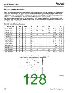
These parameters are important in determining ground bounce noise and inductive crosstalk noise. Three capaci-
tances in pF are listed: CM, the mutual capacitance of the lead to the nearest neighbor lead; and C1 and C2, the
total capacitance of the lead to all other leads (all other leads are assumed to be grounded). These parameters are
important in determining capacitive crosstalk and the capacitive loading effect of the lead.
The parasitic values in Table 30 are for the circuit model of bond wire and package lead parasitics. If the mutual
capacitance value is not used in the designer’s model, then the value listed as mutual capacitance should be added
to each of the C1 and C2 capacitors.
Table 30. Series 2 Package Parasitics
Package Type
LSW
LMW
RW
C1
C2
CM
LSL
LML
84-Pin PLCC
3
3
3
4
4
4
4
4
5
5
5
5
4
1
1
140
150
140
180
200
200
200
200
220
220
220
220
500
1
0.5
1
1
0.5
1
0.5
0.4
0.6
1
7—11
4—6
3—6
2—3
100-Pin TQFP
144-Pin TQFP
160-Pin QFP
1
4—6
2—2.5
6—8
1.5
2
1.5
1
1.5
1
10—13
7—10
6—9
208-Pin SQFP
208-Pin SQFP2
240-Pin SQFP
240-Pin SQFP2
256-Pin PBGA
304-Pin SQFP
304-Pin SQFP2
352-Pin PBGA
432-Pin EBGA
1
4—6
2
1
1
1
4—6
2
1
1
1
8—12
7—11
5—8
5—8
2
1
1
1
4—7
2
1
1
1
2—4
2
1
1
1
12—18
11—17
7—12
3—5.5
7—12
7—12
3—6
2
1
1
1
2
1.5
1
1.5
1
1.5
0.3
1.5
0.5—1
CIRCUIT
BOARD PAD
LW
RW
LL
PAD N
C1
C2
LMW
LML
CM
PAD N + 1
LW
RW
LL
C1
C2
5-3862(F).r2
Figure 53. Package Parasitics
128
Lucent Technologies Inc.

 ETC [ ETC ]