Data Sheet
June 1999
ORCA Series 2 FPGAs
is operating in the system. It is not considered a true
thermal resistance, and it is defined by:
Package Thermal Characteristics
There are three thermal parameters that are in com-
mon use: ΘJA, ψJC, and ΘJC. It should be noted that all
the parameters are affected, to varying degrees, by
package design (including paddle size) and choice of
materials, the amount of copper in the test board or
system board, and system airflow.
TJ – TC
ψ
JC = -------------------
Q
where TC is the case temperature at top dead center,
TJ is the junction temperature, and Q is the chip power.
During the ΘJA measurements described above,
besides the other parameters measured, an additional
temperature reading, TC, is made with a thermocouple
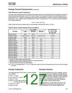
The data base containing the thermal values for all of
Lucent Technologies’ IC packages is currently being
updated to conform to modern JEDEC standards.
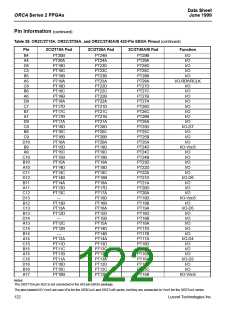
Thus, Table 29 contains the currently available thermal
specifications for Lucent Technologies’ FPGA pack-
ages mounted on both JEDEC and non-JEDEC test
boards. The thermal values for the newer package
types correspond to those packages mounted on a
JEDEC four-layer board (indicated as Note 2 in the
table). The values for the older packages, however, cor-
respond to those packages mounted on a non-JEDEC,
single-layer, sparse copper board (see Note 1). It
should also be noted that the values for the older pack-
ages are considered conservative.
ψJC is also
attached at top-dead-center of the case.
expressed in units of °C/watt.
ΘJC
This is the thermal resistance from junction to case. It
is most often used when attaching a heat sink to the
top of the package. It is defined by:
TJ – TC
ΘJC
= -------------------
Q
The parameters in this equation have been defined
above. However, the measurements is performed with
the case of the part pressed against a water-cooled
heat sink so as to draw most of the heat generated by
the chip out the top of the package. It is this difference
in the measurement process that differentiates ΘJC
ΘJA
This is the thermal resistance from junction to ambient
(a.k.a. theta-JA, R-theta, etc.).
ψJC. ΘJC is a true thermal resistance and is
from
expressed in units of °C/watt.
TJ – TA
ΘJA = -------------------
Q
ΘJB
where TJ is the junction temperature, TA is the ambient
air temperature, and Q is the chip power.
This is the thermal resistance from junction to board
(a.k.a., ΘJL). It is defined by:
Experimentally, ΘJA is determined when a special ther-
mal test die is assembled into the package of interest,
and the part is mounted on the thermal test board. The
diodes on the test chip are separately calibrated in an
oven. The package/board is placed either in a JEDEC
natural convection box or in the wind tunnel, the latter
for forced convection measurements. A controlled
amount of power (Q) is dissipated in the test chip’s
heater resistor, the chip’s temperature (TJ) is deter-
mined by the forward drop on the diodes, and the ambi-
ent temperature (TA) is noted. Note that ΘJA is
expressed in units of °C/watt.
TJ – TB
ΘJB = -------------------
Q
where TB is the temperature of the board adjacent to a
lead measured with a thermocouple. The other param-
eters on the right-hand side have been defined above.
This is considered a true thermal resistance, and the
measurement is made with a water-cooled heat sink
pressed against the board so as to draw most of the
heat out of the leads. Note that ΘJB is expressed in
units of °C/watt, and that this parameter and the way it
is measured is still in JEDEC committee.
ψ
JC
This JEDEC designated parameter correlates the junc-
tion temperature to the case temperature. It is generally
used to infer the junction temperature while the device
Lucent Technologies Inc.
126

 ETC [ ETC ]