Data Sheet
June 1999
ORCA Series 2 FPGAs
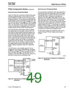
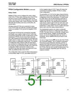
Slave Parallel Mode
FPGA Configuration Modes (continued)
The slave parallel mode is essentially the same as the
slave serial mode except that 8 bits of data are input on
pins D[7:0] for each CCLK cycle. Due to 8 bits of data
being input per CCLK cycle, the DOUT pin does not
contain a valid bit stream for slave parallel mode. As a
result, the lead device cannot be used in the slave
parallel mode in a daisy-chain configuration.
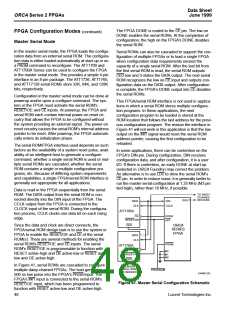
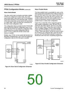
Slave Serial Mode
The slave serial mode is primarily used when multiple
FPGAs are configured in a daisy chain. The serial
slave serial mode is also used on the FPGA evaluation
board which interfaces to the download cable. A device
in the slave serial mode can be used as the lead device
in a daisy chain. Figure 44 shows the connections for
the slave serial configuration mode.
Figure 45 is a schematic of the connections for the
slave parallel configuration mode. WR and CS0 are
active-low chip select signals, and CS1 is an active-
high chip select signal. These chip selects allow the
user to configure multiple FPGAs in slave parallel
mode using an 8-bit data bus common to all of the
FPGAs. These chip selects can then be used to select
the FPGA(s) to be configured with a given bit stream,
but once an FPGA has been selected, it cannot be
deselected until it has been completely programmed.
The configuration data is provided into the FPGA’s DIN
input synchronous with the configuration clock CCLK
input. After the FPGA has loaded its configuration data,
it retransmits the incoming configuration data on
DOUT. CCLK is routed into all slave serial mode
devices in parallel.
Multiple slave FPGAs can be loaded with identical con-
figurations simultaneously. This is done by loading the
configuration data into the DIN inputs in parallel.
8
D[7:0]
DONE
TO DAISY-
CHAINED
DEVICES
INIT
DOUT
ORCA
SERIES
FPGA
CCLK
MICRO-
PROCESSOR
OR
PRGM
VDD
SYSTEM
INIT
ORCA
SERIES
FPGA
MICRO-
PROCESSOR
OR
DOWNLOAD
CABLE
CS1
CS0
WR
PRGM
DONE
CCLK
DIN
M2
M1
M0
HDC
LDC
VDD
M2
M1
M0
HDC
LDC
5-4487(F)
Figure 45. Slave Parallel Configuration Schematic
5-4485(F)
Figure 44. Slave Serial Configuration Schematic
50
Lucent Technologies Inc.

 ETC [ ETC ]