Data Sheet
June 1999
ORCA Series 2 FPGAs
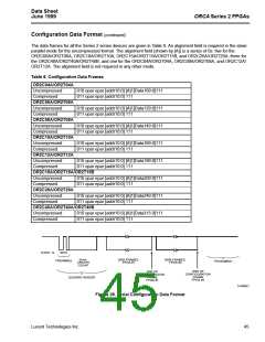
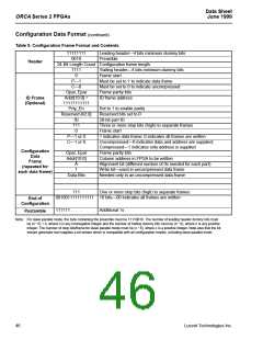
Configuration Data Format (continued)
Table 9. Configuration Frame Format and Contents
11111111
0010
Leading header—4 bits minimum dummy bits
Preamble
Header
24-Bit Length Count Configuration frame length
1111
0
Trailing header—4 bits minimum dummy bits
Frame start
P—1
C—0
Must be set to 1 to indicate data frame
Must be set to 0 to indicate uncompressed
Frame parity bits
Opar, Epar
Addr[10:0] =
11111111111
Prty_En
Reserved [42:0]
ID
ID Frame
(Optional)
ID frame address
Set to 1 to enable parity
Reserved bits set to 0
20-bit part ID
111
0
Three or more stop bits (high) to separate frames
Frame start
P—1 or 0
C—1 or 0
1 indicates data frame; 0 indicates all frames are written
Uncompressed—0 indicates data and address are supplied;
Compressed—1 indicates only address is supplied
Frame parity bits
Configuration
Data
Frame
(repeated for
each data frame)
Opar, Epar
Addr[10:0]
Column address in FPGA to be written
Alignment bit (different number of 0s needed for each part)
Write bit—used in uncompressed data frame
Needed only in an uncompressed data frame
.
A
1
Data Bits
.
.
.
111
One or more stop bits (high) to separate frames
0010011111111111 16 bits—00 indicates all frames are written
End of
Configuration
111111 . . . . . Additional 1s
Postamble
Note: For slave parallel mode, the byte containing the preamble must be 11110010. The number of leading header dummy bits must
be (n * 8) + 4, where n is any nonnegative integer and the number of trailing dummy bits must be (n * 8), where n is any positive
integer. The number of stop bits/frame for slave parallel mode must be (x * 8), where x is a positive integer. Note also that the bit
stream generator tool supplies a bit stream which is compatible with all configuration modes, including slave parallel mode.
46
Lucent Technologies Inc.

 ETC [ ETC ]