11.2.2
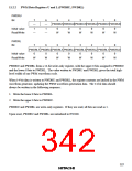
PWM Data Registers U and L (PWDRU, PWDRL)
PWDRU
Bit
7
—
1
6
—
1
5
4
3
2
1
0
PWDRU5PWDRU4PWDRU3PWDRU2 PWDRU1PWDRU0
Initial value
Read/Write
0
0
0
0
0
0
—
—
W
W
W
W
W
W
PWDRL
Bit
7
6
5
4
3
2
1
0
PWDRL7 PWDRL6 PWDRL5 PWDRL4 PWDRL3 PWDRL2 PWDRL1 PWDRL0
Initial value
Read/Write
0
0
0
0
0
0
0
0
W
W
W
W
W
W
W
W
PWDRU and PWDRL form a 14-bit write-only register, with the upper 6 bits assigned to PWDRU
and the lower 8 bits to PWDRL. The value written to PWDRU and PWDRL gives the total high-
level width of one PWM waveform cycle.
When 14-bit data is written to PWDRU and PWDRL, the register contents are latched in the PWM
waveform generator, updating the PWM waveform generation data. The 14-bit data should
always be written in the following sequence:
1. Write the lower 8 bits to PWDRL.
2. Write the upper 6 bits to PWDRU.
PWDRU and PWDRL are write-only registers. If they are read, all bits are read as 1.
Upon reset, PWDRU and PWDRL are initialized to H'C000.
327

 ETC [ ETC ]