11.2
Register Descriptions
11.2.1
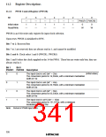
PWM Control Register (PWCR)
Bit
7
—
1
6
—
1
5
—
1
4
—
1
3
—
1
2
—
1
1
0
PWCR1 PWCR0
Initial value
Read/Write
0
0
—
—
—
—
—
—
W
W
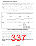
PWCR is an 8-bit write-only register for input clock selection.
Upon reset, PWCR is initialized to H'FC.
Bits 7 to 2: Reserved bits
Bits 7 to 2 are reserved; they are always read as 1, and cannot be modified.
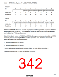
Bits 1 and 0: Clock select 1 and 0 (PWCR1, PWCR0)
Bits 1 and 0 select the clock supplied to the 14-bit PWM. These bits are write-only bits; they are
always read as 1.
Bit 1
Bit 0
PWCR1 PWCR0 Description
0
0
1
1
0
1
0
1
The input clock is ø/2 (tø* = 2/ø)
The conversion period is 16,384/ø, with a minimum modulation
width of 1/ø
(initial value)
The input clock is ø/4 (tø* = 4/ø)
The conversion period is 32,768/ø, with a minimum modulation
width of 2/ø
The input clock is ø/8 (tø* = 8/ø)
The conversion period is 65,536/ø, with a minimum modulation
width of 4/ø
The input clock is ø/16 (tø* = 16/ø)
The conversion period is 131,072/ø, with a minimum
modulation width of 8/ø
Note: Period of PWM input clock.
326

 ETC [ ETC ]