11.3
Operation
11.3.1
Operation
When using the 14-bit PWM, set the registers in the following sequence.
1. Set bit PWM in port mode register 3 (PMR3) to 1 so that pin P30/PWM is designated for
PWM output.
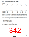
2. Set bits PWCR1 and PWCR0 in the PWM control register (PWCR) to select a conversion
period of 131,072/ø (PWCR1 = 1, PWCR0 = 1), 65,536/ø (PWCR1 = 1, PWCR0 = 0),
32,768/ø (PWCR1 = 0, PWCR0 = 1), or 16,384/ø (PWCR1 = 0, PWCR0 = 0).
3. Set the output waveform data in PWM data registers U and L (PWDRU/L). Be sure to write in
the correct sequence, first PWDRL then PWDRU. When data is written to PWDRU, the data
in these registers will be latched in the PWM waveform generator, updating the PWM
waveform generation in synchronization with internal signals.
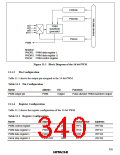
One conversion period consists of 64 pulses, as shown in figure 11-2. The total of the high-
level pulse widths during this period (TH) corresponds to the data in PWDRU and PWDRL.
This relation can be represented as follows.
TH = (data value in PWDRU and PWDRL + 64) × tø/2
where tø is the PWM input clock period: 2/ø (PWCR = H'0), 4/ø (PWCR = H'1), 8/ø (PWCR =
H'2), or 16/ø (PWCR = H'3).
Example: Settings in order to obtain a conversion period of 32,768 µs:
When PWCR1 = 0 and PWCR0 = 0, the conversion period is 16,384/ø, so ø must be 0.5
MHz. In this case, tfn = 512 µs, with 1/ø (resolution) = 2.0 µs.
When PWCR1 = 0 and PWCR0 = 1, the conversion period is 32,768/ø, so ø must be 1
MHz. In this case, tfn = 512 µs, with 2/ø (resolution) = 2.0 µs.
When PWCR1 = 1 and PWCR0 = 0, the conversion period is 65,536/ø , so ø must be 2
MHz. In this case, tfn = 512 µs, with 4/ø (resolution) = 2.0 µs.
Accordingly, for a conversion period of 32,768 µs, the system clock frequency (ø) must
be 0.5 MHz, 1 MHz, or 2 MHz.
329

 ETC [ ETC ]