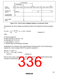
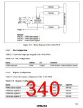
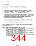
PWDRL
PWDRU
ø/2
ø/4
PWM
waveform
generator
ø/8
ø/16
PWCR
PWM
Notation:
PWDRL: PWM data register L
PWDRU: PWM data register U
PWCR: PWM control register
Figure 11-1 Block Diagram of the 14 bit PWM
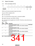
Pin Configuration
11.1.3
Table 11-1 shows the output pin assigned to the 14-bit PWM.
Table 11-1 Pin Configuration
Name
Abbrev.
I/O
Function
PWM output pin
PWM
Output
Pulse-division PWM waveform output
11.1.4
Register Configuration
Table 11-2 shows the register configuration of the 14-bit PWM.
Table 11-2 Register Configuration
Name
Abbrev.
PWCR
R/W
W
Initial Value
H'FC
Address
H'FFD0
H'FFD1
H'FFD2
H'FFFB
PWM control register
PWM data register U
PWM data register L
Clock stop register 2
PWDRU
PWDRL
CKSTPR2
W
H'C0
W
H'00
R/W
H'FF
325

 ETC [ ETC ]