APEX 20K Programmable Logic Device Family Data Sheet
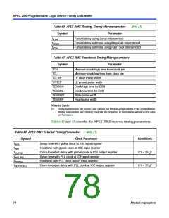
Table 40. APEX 20KE Routing Timing Microparameters
Note (1)
Symbol
Parameter
t
t
t
Fanout delay using Local Interconnect
F1-4
Fanout delay estimate using MegaLab Interconnect
Fanout delay estimate using FastTrack Interconnect
F5-20
F20+
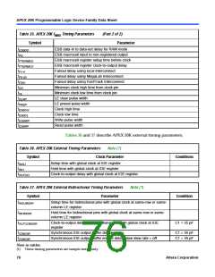
Table 41. APEX 20KE Functional Timing Microparameters
Symbol
Parameter
TCH
Minimum clock high time from clock pin
Minimum clock low time from clock pin
LE clear Pulse Width
TCL
TCLRP
TPREP
TESBCH
TESBCL
TESBWP
TESBRP
LE preset pulse width
Clock high time for ESB
Clock low time for ESB
Write pulse width
Read pulse width
Note to Table:
(1) These parameters are worst-case values for typical applications. Post-compilation
timing simulation and timing analysis are required to determine actual worst-case
performance.
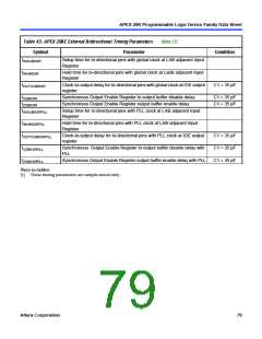
Tables 42 and 43 describe the APEX 20KE external timing parameters.
Table 42. APEX 20KE External Timing Parameters
Note (1)
Symbol
Clock Parameter
Conditions
t
t
t
t
t
t
Setup time with global clock at IOE input register
Hold time with global clock at IOE input register
Clock-to-output delay with global clock at IOE output register
Setup time with PLL clock at IOE input register
Hold time with PLL clock at IOE input register
INSU
INH
C1 = 35 F
OUTCO
p
INSUPLL
INHPLL
Clock-to-output delay with PLL clock at IOE output register
C1 = 35 F
OUTCOPLL
p
78
Altera Corporation

 ETC [ ETC ]