Philips Semiconductors
Product specification
Silicon diffused power transistors
BUT18F; BUT18AF
SYMBOL
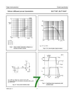
hFE
PARAMETER
DC current gain
CONDITIONS
MIN.
10
TYP. MAX. UNIT
VCE = 5 V; IC = 10 mA;
see Fig.9
18
35
VCE = 5 V; IC = 1 A; see Fig.9
10
20
35
Switching times resistive load (see Figs 10 and 11)
ton
ts
turn-on time
storage time
fall time
ICon = 4 A;
Bon = −IBoff = 800 mA
−
−
−
−
−
−
1
µs
µs
µs
I
ICon = 4 A;
IBon = −IBoff = 800 mA
4
tf
ICon = 4 A;
0.8
IBon = −IBoff = 800 mA
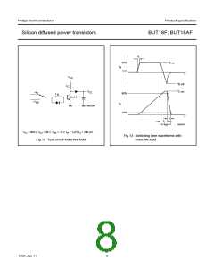
Switching times inductive load (see Figs 10 and 13)
ts
tf
storage time
fall time
ICon = 4 A; IBon = 800 mA
ICon = 4 A; IBon = 800 mA
−
−
1.6
2.5
µs
150
400
ns
Note
1. Measured with a half-sinewave voltage (curve tracer).
MGK674
120
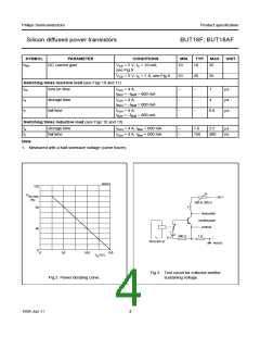
handbook, halfpage
handbook, halfpage
P
tot max
(%)
+ 50 V
100 to 200 Ω
L
80
horizontal
oscilloscope
vertical
40
300 Ω
1 Ω
6 V
30 to 60 Hz
MGE252
0
0
50
100
150
o
T
( C)
h
Fig.3 Test circuit for collector-emitter
sustaining voltage.
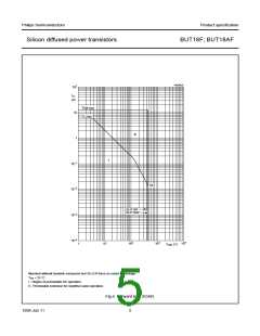
Fig.2 Power derating curve.
1999 Jun 11
4

 ETC [ ETC ]