Philips Semiconductors
Product specification
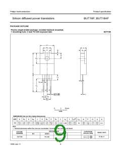
Silicon diffused power transistors
BUT18F; BUT18AF
LIMITING VALUES
In accordance with the Absolute Maximum Rating System (IEC 134).
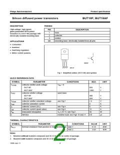
SYMBOL
PARAMETER
CONDITIONS
MIN.
MAX.
UNIT
VCESM
collector-emitter peak voltage
BUT18F
VBE = 0
−
−
850
V
V
BUT18AF
1000
VCEO
collector-emitter voltage
BUT18F
open base
−
−
−
−
−
−
−
−
−
400
450
4
V
V
A
A
A
A
A
W
W
BUT18AF
ICsat
IC
ICM
IB
collector saturation current
collector current (DC)
collector current (peak value)
base current (DC)
base current (peak value)
total power dissipation
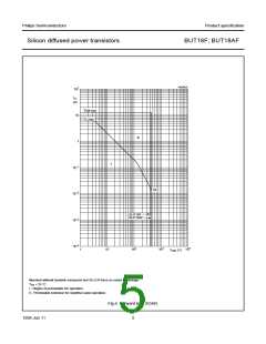
see Fig.4
see Fig.4
6
12
3
IBM
Ptot
6
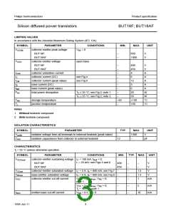
Th ≤ 25 °C; see Fig.2; note 1
Th ≤ 25 °C; see Fig.2; note 2
20
33
+150
150
Tstg
Tj
storage temperature
junction temperature
−65
°C
°C
−
Notes
1. Without heatsink compound.
2. With heatsink compound.
ISOLATION CHARACTERISTICS
SYMBOL
PARAMETER
TYP.
MAX.
UNIT
VisolM
Cisol
isolation voltage from all terminals to external heatsink (peak value)
isolation capacitance from collector to external heatsink
−
1500
V
12
−
pF
CHARACTERISTICS
Tj = 25 °C unless otherwise specified.
SYMBOL
PARAMETER
CONDITIONS
MIN.
TYP. MAX. UNIT
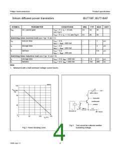
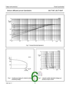
VCEOsust
collector-emitter sustaining voltage IC = 100 mA; IBoff = 0;
L = 25 mH; see Figs 3 and 6
BUT18F
400
450
−
−
−
−
−
−
−
V
BUT18AF
−
V
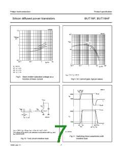
VCEsat
VBEsat
ICES
collector-emitter saturation voltage IC = 4 A; IB = 800 mA; see Fig.7
1.5
1.3
1
V
base-emitter saturation voltage
collector-emitter cut-off current
IC = 4 A; IB = 800 mA; see Fig.8
−
V
VCE = VCESMmax; VBE = 0;
note 1
−
mA
V
CE = VCESMmax; VBE = 0;
−
−
−
−
2
mA
mA
Tj = 125 °C; note 1
IEBO
emitter-base cut-off current
VEB = 9 V; IC = 0
10
1999 Jun 11
3

 ETC [ ETC ]