Si3210/Si3211/Si3212
Table 31. Associated Pulse Metering Generator Registers
Parameter
Description / Range
Register Bits
Location
Pulse Metering Frequency
Coefficient
Sets oscillator frequency
PLSCO[15:0]
Indirect Register 25
Pulse Metering Amplitude
Coefficient
Sets oscillator amplitude
0 to PLSX (full amplitude)
PLSX[15:0]
PLSD[15:0]
Indirect Register 24
Indirect Register 23
Pulse Metering Attack/Decay
Ramp Rate
Pulse Metering Active Timer
Pulse Metering Inactive Timer
Pulse Metering Control
0 to 8 sec
0 to 8 sec
PAT[15:0]
PIT[15:0]
Direct Registers 44 & 45
Direct Register 46 & 47
Direct Register 35
Status and control registers
PSTAT, PMAE,
PMIE, PMOE
Note: The ProSLIC uses registers that are both directly and indirectly mapped. A “direct” register is one that is mapped
directly. An “indirect” register is one that is accessed using the indirect access registers (direct registers 28
through 31).
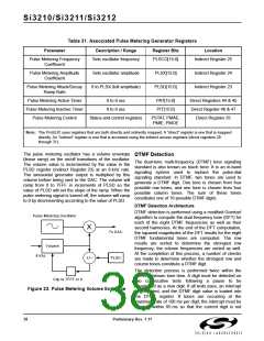
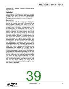
The pulse metering oscillator has a volume envelope
DTMF Detection
(linear ramp) on the on/off transitions of the oscillator.
The dual-tone multi-frequency (DTMF) tone signaling
The volume value is incremented by the value in the
standard is also known as touch tone. It is an in-band
PLSD register (indirect Register 23) at an 8 kHz rate.
signaling system used to replace the pulse-dial
The sinusoidal generator output is multiplied by this
signaling standard. In DTMF, two tones are used to
volume before being sent to the DAC. The volume will
generate a DTMF digit. One tone is chosen from four
ramp from 0 to 7FFF in increments of PLSD so the
possible row tones, and one tone is chosen from four
value of PLSD will set the slope of the ramp. When the
possible column tones. The sum of these tones
pulse metering signal is turned off, the volume will ramp
constitutes one of 16 possible DTMF digits.
to 0 by decrementing according to the value of PLSD.
DTMF Detection Architecture
DTMF detection is performed using a modified Goertzel
algorithm to compute the dual frequency tone (DFT) for
Pulse Metering Oscillator
each of the eight DTMF frequencies as well as their
X
second harmonics. At the end of the DFT computation,
the squared magnitudes of the DFT results for the eight
To DAC
DTMF fundamental tones are computed. The row
results are sorted to determine the strongest row
frequency; the column frequencies are sorted as well.
Volume
At the completion of this process, a number of checks
are made to determine whether the strongest row and
column tones constitute a DTMF digit.
8 Khz
PLSD
+/–
The detection process is performed twice within the
45 ms minimum tone time. A digit must be detected on
Clip to 7FFF or 0
two consecutive tests following
a pause to be
recognized as a new digit. If all tests pass, an interrupt
is generated, and the DTMF digit value is loaded into
the DTMF register. If tones are occurring at the
maximum rate of 100 ms per digit, the interrupt must be
serviced within 85 ms so that the current digit is not
Figure 22. Pulse Metering Volume Envelope
38
Preliminary Rev. 1.11

 ETC [ ETC ]