Si3035
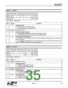
Register 1. Control 1
Bit
D7
D6
D5
D4
D3
D2
D1
D0
Name SR
Type R/W
DL
SB
R/W R/W
Reset settings = 0000_0000
Bit
Name
Function
7
SR
Software Reset.
0 = Enables chip for normal operation.
1 = Sets all registers to their reset value.
6:2
1
Reserved Read returns zero.
DL
Isolation Digital Loopback.
0 = Disables digital loopback mode across the isolation barrier.
1 = Enables digital loopback mode across the isolation barrier.
0
SB
Serial Digital Interface Mode.
0 = Operation is in 15-bit mode and the LSB of the data field indicates whether a secondary
frame is required.
1 = The serial port is operating in 16-bit mode and requires use of the secondary frame sync
signal, FC/RGDT, to initiate control data reads/writes.
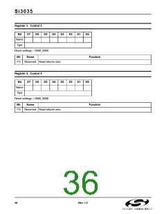
Register 2. Control 2
Bit
D7
D6
D5
D4
D3
AL
D2
D1
D0
Name
Type
HBE RXE
R/W R/W
R/W
Reset settings = 0000_0011
Bit
7:4
3
Name
Reserved Read returns zero.
AL Analog Loopback.
Function
0 = Disables analog loopback mode.
1 = Enables analog loopback mode.
2
1
Reserved Read returns zero.
HBE
Hybrid Enable.
0 = Disconnects hybrid in transmit path.
1 = Connects hybrid in transmit path.
0
RXE
Receive Enable.
0 = Disables receive path.
1 = Enables receive path.
Rev. 1.2
35

 ETC [ ETC ]