Si3035
Analog Output
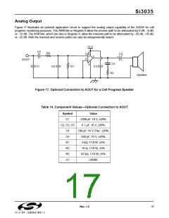
Figure 17 illustrates an optional application circuit to support the analog output capability of the Si3035 for call
progress monitoring purposes. The ARM bits in Register 6 allow the receive path to be attenuated by 0 dB, –6 dB,
or –12 dB. The ATM bits, which are also in Register 6, allow the transmit path to be attenuated by –20 dB, –26 dB,
or –32 dB. Both the transmit and receive paths can also be independently muted.
+5 V
C2
6
R3
3
2
C4
+
–
5
+
AOUT
C5
4
C1
C6
R1
C3
R2
Speaker
Figure 17. Optional Connection to AOUT for a Call Progress Speaker
Table 14. Component Values—Optional Connection to AOUT
‘
Symbol
Value
C1
C2, C3, C5
C4
2200 pF, 16 V, ±20%
0.1 µF, 16 V, ±20%
100 µF, 16 V, Elec. ±20%
820 pF, 16 V, ±20%
3 kΩ, 1/10 W, ±5%
10 Ω, 1/10 W, ±5%
47 kΩ, 1/10 W, ±5%
LM386
C6
R1
R2
R3
U1
Rev. 1.2
17

 ETC [ ETC ]