Version: 1.18
PRELIMINARY/CONFIDENTIAL
TrueSpeech® Co-Processor
4.6.2
Burst Mode and Single Cycle Mode Transfers
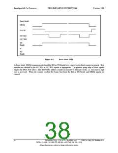
DMA transfers can be performed in either Burst Mode (continuous) or Single Cycle Mode. In Burst Mode, the
DMA request signal TXDREQ or RXDREQ remains asserted whenever the appropriate data buffer can
accommodate the transfer. Each time the DMA acknowledge signal, TXDACKN + HSTWRN or RXDACKN +
HSTRDN, is asserted a byte is transferred. This continues until the Transmit Data Buffer is full or the Receive Data
Buffer is empty, at which point the DMA request signal is de-asserted (the appropriate TX or RX Ready bit is
cleared). Burst Mode allows for the fastest transfer of data, since the Host is required to perform bus request/bus
grant arbitration with it’s external DMA controller only once per burst. With a 16-word buffer, up to 32 bytes can be
transferred in a single burst.
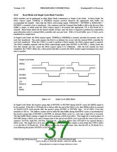
In Single Cycle Mode, the DMA request signal, TXDREQ or RXDREQ is asserted, and then de-asserted, once for
each byte transferred. This mode requires the Host to re-arbitrate bus access with the external DMA controller for
each byte transferred. When the CT8022 is ready to perform a DMA transfer, the DMA request signal is asserted.
The DMA controller responds with the DMA acknowledge signal (plus HSTRD/ or HSTWR/ ), which clocks the
byte data transfer and also causes the DMA request signal to be withdrawn. After the byte transfer has been
completed, the CT8022 delays for a short period and then re-asserts the DMA request signal (assuming it has more
data to transfer).
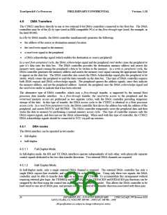
Single Cycle Mode
DREQ
DACK/
HSTRD/
HSTWR/
TX
Ready or
RX
Ready
Figure 4-4:
Single Cycle DMA Mode
In Single Cycle Mode, the negative going edge of HSTRD/ or HSTWR/ during DACK/ causes the DREQ signal to
be de-asserted. If the RX or TX Ready bit is still set after the end of the DMA cycle, then DREQ will be re-asserted
16 MAINCLOCK clock periods after the positive going HSTRD/ or HSTWR/ edge. At 40 MIPS (25ns) this
translates to 400 ns. The address counter used to index the data buffer during Host/DMA cycles is incremented by
the positive going edge of HSTRD/ or HSTWR/ on alternate DMA cycles (i.e. each time a high byte is accessed).
The data buffer block contains a toggle bit used to generate a DMA byte select. This toggle bit is used in place of
HSTAB0 during a DMA cycle, and it changes state at the end of each DMA cycle to provide the correct byte access
sequence: low-byte, high-byte, low-byte, high-byte etc. The Host address lines HSTAB3-0 are ignored during a
DMA cycle. The toggle bit is set to zero each time the data buffer address counter is reset (when the CT8022 writes
a 1 to the RX or TX Ready bit). If the counter reaches the Frame Size limit value, then the RX or TX Ready bit is
reset following the positive HSTRD/ or HSTWR/ edge.
CT8022A11AQC FW Revision 0118 DSP GROUP, INC., 3120 SCOTT BOULEVARD
SANTA CLARA, CA 95054 PH: 408 986 – 4300 FAX: 408 986 – 4490
37
All specifications are subject to change without prior notice.

 ETC [ ETC ]