TrueSpeech® Co-Processor
PRELIMINARY/CONFIDENTIAL
Version: 1.18
4.6
DMA Transfers
The CT8022 interfaces directly to one or two external 8-bit DMA controllers connected to the Host bus. The DMA
controllers may be of the fly-by type (used in IBM-compatible PCs) or the flow-through type (used, for example, in
the Intel 80186).
In a fly-by DMA transfer, the DMA controller simultaneously generates the following:
•
•
•
•
the address of the source or destination memory location
the read/write signal to the memory
a read/write signal to the peripheral
a DMA acknowledge signal (which enables the destination or source peripheral)
In a read from peripheral cycle, the DMA acknowledge signal and the peripheral read strobe cause the peripheral to
gate it’s data onto the data bus. The DMA controller provides the destination memory address and asserts the
memory write signal causing the peripheral’s data to be written to the memory. In a write to peripheral cycle, the
DMA controller generates the memory address and asserts the memory read signal causing the appropriate data byte
to appear on the data bus. The DMA controller also asserts the DMA Acknowledge signal plus the peripheral write
strobe, which causes the peripheral to read the data currently on the data bus. This type of DMA controller requires
both DMA request and DMA acknowledge signals. The peripheral ignores the address signals, since they indicate
the memory address, and not the peripheral address. Instead, the peripheral uses the DMA acknowledge signal and
the read/write strobe to indicate that it has been selected.
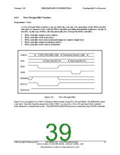
The alternative type of DMA controller, which uses a flow-through transfer, is supported by the normal Host
processor data transfer interface. In a flow-through transfer, the read/write access to the peripheral and the
write/read memory access are performed as two separate cycles, with the DMA controller providing temporary
storage of the data. In this type of transfer, the DMA access cycle to the CT8022 is identical to a Host processor
access cycle. In a read from peripheral cycle, the DMA controller first drives the address bus with the address of the
peripheral, and asserts HSTCS/ and HSTRD/. The DMA controller temporarily saves the peripheral data and then
writes the data to memory by performing a normal memory access cycle. This type of controller requires only the
DMA request signals, and does not use the DMA acknowledge. When used with this type of controller, the CT8022
DMA acknowledge signals should be connected to VCC via pull-up resistors.
4.6.1
DMA modes
The DMA interface can be operated in two modes:
•
•
full-duplex
half-duplex
4.6.1.1
Full-Duplex Mode
In full-duplex mode, the RX and TX DMA interfaces operate independently of each other, with physically separate
control signals dedicated to the two data transfer directions. Two external DMA channels are required.
4.6.1.2
Half-Duplex Mode
In half-duplex mode, only a single external DMA channel is required. The external DMA controller has only a
single DMA request line available, and a single DMA acknowledge line. Using only these two signals, the DMA
controller must be able to transfer data both to and from the CT8022. To accommodate this arrangement without
requiring external glue logic, the TXDREQ and RXDREQ and the TXDACKN and RXDACKN pin functions can be
swapped by the Host using the control bits in the Hardware Control Register. This allows the DMA controller to be
hard-wired to one set of DMA pins, and permits software control of the transfer direction associated with these pins.
36
DSP GROUP, INC., 3120 SCOTT BOULEVARD CT8022A11AQC FW Revision 0118
SANTA CLARA, CA 95054 PH: 408 986 – 4300 FAX: 408 986 – 4490
All specifications are subject to change without prior notice.

 ETC [ ETC ]