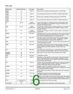
Pin List
Mnemonic:
Pad and Pin No.:
Pin Type:
Description:
SDIP
SDIN
4
5
CML IN
Data inputs. Internally terminated with 50 W to TDIP/TDIN.
TDIP
TDIN
3
6
CML IN
CML IN
CML IN
Loop through termination pins for SDIP and SDIN respectively.
Clock inputs. Internally terminated with 50 W to TCIP/TCIN.
Loop through termination pins for SDIP and SDIN respectively.
SCIP
SCIN
9
10
TCIP
TCIN
8
11
IM
29, 30
OPEN
COLLECTOR
Laser Driver Output (2.5 Gbit/s). IM sinks a modulation current,
which is controlled by the pin IMSET. A logic HI on SDIP corre-
sponds to IM sinking current.
IMB
31, 32
OPEN
COLLECTOR
Laser Driver inverted Output (2.5 Gbit/s). IMB sinks a modulation
current, which is controlled by the pin IMSET. Connect to VCC
through 20 to 25 W.
IB
27
40
OPEN
COLLECTOR
Pre-bias current output. IB sinks a current, which is controlled by
the pin IMC.
IMSET
ANL OUT
Modulation current control monitor output. This pin is the output of
the modulation current control loop OP-amp. For stability a capa-
citor may be added between this pin and the IMC pin.
IBSET
22
ANL OUT
Pre-bias current control monitor output. This pin is the output of
the optical power control loop OP-amp. For stability a capacitor
may be added between this pin and the OPSET pin.
IBM
IMM
23
39
ANL OUT
ANL OUT
Pre-bias current mirror output. The sink current into the IBM pin is
1/20 of the pre-bias current.
Modulation current mirror output. The sink current into the IMM
pin is 1/20 of the modulation current. Internally IMM is connected
to the positive input of the modulation current control loop
OP-amp.
AR
25
ANL OUT
ANL OUT
Anti-rush current sink. AR sinks a 1 mA current when SHDW is
high. Typically connected together with PD to the monitor diode.
MARKP
MARKN
35
36
Mark-space monitor outputs. High impedance CML outputs.
MTJ
IMC
38
41
ANL OUT
ANL IN
Temperature monitor.
Modulation current setting. The modulation current will automati-
cally be adjusted to this value if the internal modulation control
loop is used. The IMC pin is the negative input of the modulation
current control loop OP-amp.
PD
26
19
ANL IN
ANL IN
Positive input of the automatic optical power control loop OP-amp,
used to control the pre-bias current. Typically connected to the
monitor diode photo detector of the laser diode.
OPSET
Negative input of the automatic optical power control loop
OP-amp, used to control the pre-bias current. Typically connected
to an external reference voltage.
FFSET
SHDW
DUTY
15
16
48
LVTTL IN
LVTTL IN
ANL IN
When FFSET is low data is re-timed. When high data re-timing is
bypassed.
Modulation and pre-bias current shutdown input.
Set high for shutdown, low for normal operation.
Input for control of the mark-space ratio of the output. Decreasing
the voltage of the DUTY pin increases the pulse width of a current
high into the IM pin. Typically connected to VEE through resistor.
VCC
14, 18, 20, 28, 33,
42, 46
PWR
PWR
Positive supply pins for laser driver part.
VCCCONT
44
Positive supply pin for modulation current control system.
Data Sheet Rev.: 11
GD16521
Page 6 of 13

 ETC [ ETC ]