VCC
0.1 nH
chip R
(0 ~ 15 ohm)
0.05 pF
0.02 pF
0.10 pF
0.02 pF
0.02 pF
0.10 pF
0.05 pF
6 ohm 1.0 V
0.1 nH
0.6 nH
0.1 nH
0.3 nH
0.7 nH
*2
*3
3 pF
LDD
0.1 nH
chip R (0 ~ 50 ohm)
chip C (0 ~ 0.1 uF)
IMB
IM
IB
0.05 pF
0.04 pF
0.04 pF
0.04 pF
0.04 pF
0.02 pF
0.1 ohm
R
0.01 nH
chip C equivalent circuit
C
chip R equivalent circuit
LDD IC
note1 :
Chip component constants mean available range.
This circuit is applied to all temperature range.
note2 :
on-chip stray elements
on-chip R, if necessary
note3 :
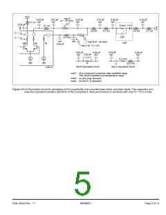
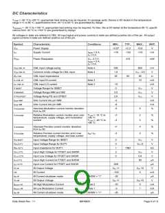
Figure 10.LD Equivalent circuit for simulating of DC coupled flip chip mounted laser driver and laser diode. The capacitors and
inductors represent paratisiv elements of the connections. Best performance is achieved with chip R = 10 W in bias.
Data Sheet Rev.: 11
GD16521
Page 5 of 13

 ETC [ ETC ]