ZENTRUM MIKROELEKTRONIK DRESDEN AG
“ASI for you” IC
Datasheet
1
General Device Specification
1.1 Absolute Maximum Ratings (Non Operating)
Table 1: Absolute Maximum Ratings
Symbol
Parameter
Min
0
Max
Unit Note
V
V0V, VGND
VASIP-ASIN
Voltage reference
0
40
1
Voltage difference between ASIP and ASIN (VASIP - VASIN
)
-0.3
-0.3
-0.3
-6.0
-0.3
-0.3
V
2
VASIP-ASIN_P Pulse voltage between ASIP and ASIN (VASIP - VASIN
)
50
V
2, 3
VASIP
VASIN
VUIN
Pulse voltage between ASIP and 0V (VASIP – V0V)
Voltage between ASIN and 0V (VASIN – V0V)
Power supply input voltage
50
V
3
6.0
V
40
V
V
V
2
VUIN_P
Vinputs1
Pulse voltage at power supply input
50
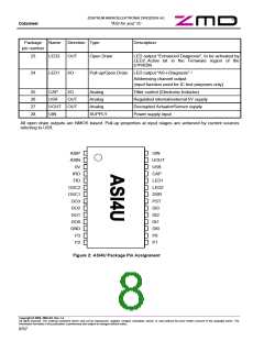
Voltage at pins DI3 ... DI0, DO3 ... DO0, P3 ... P0, DSR, PST, -0.3
LED1, LED2, FID, IRD, UOUT
VUIN + 0.3
Vinputs2
Iin
Voltage at pins OSC1, OSC2, CAP, U5R
Input current into any pin except supply pins
Humidity non-condensing
-0.3
-50
7
V
4
5
6
7
8
50
mA
H
VHBM1
VHBM2
VEDM
θSTG
Ptot
Electrostatic discharge – Human Body Model (HBM1)
Electrostatic discharge – Human Body Model (HBM2)
Electrostatic discharge – Equipment Discharge Model (EDM)
Storage temperature
3500
2000
400
V
V
V
-55
125
0.85
80
°C
W
9
Total power dissipation
10
Rthj
Thermal resistance of SSOP 28 package
40
K/W
1
reverse polarity protection has to be performed
externally
pulse with ≤ 50µs, repetition rate ≤ 0.5 Hz
VASIP-ASIN and VASIP-ASIN_P must not be violated
Latch-up resistance, reference pin is 0V
Level 4 according to JEDEC-020A is guaranteed
HBM1: C = 100pF charged to VHBM1 with resistor
R = 1.5kΩ in series, valid for ASIP-ASIN only.
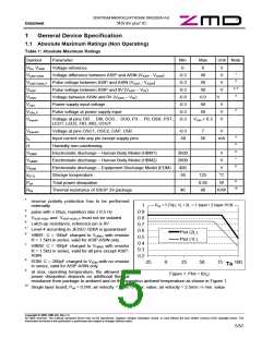
Ptot = f (Ta); 1L / 2L = 1 layer / 2 layer PCB
1
0.9
0.8
0.7
0.6
0.5
0.4
0.3
0.2
2
3
4
5
6
Ptot (2L)
Ptot (1L)
7
HBM2: C = 100pF charged to VHBM2 with resistor
R = 1.5kΩ in series, valid for all pins except ASIP-
ASIN
8
9
EDM: C = 200pF charged to VEDM with no resistor
-25
0
25
50
75
100
Ta
in series, valid for ASIP-ASIN only
at max. operating temperature, the allowed total
power dissipation depends on additional thermal
resistance from package to ambient and on the operation ambient temperature as shown in Figure 1.
10
Single layer board, Ptot = 0.5W; air velocity = 0m/s ⇒ max. value; air velocity = 2.5m/s ⇒ min. value
Copyright © 2006, ZMD AG, Rev.1.4
All rights reserved. The material contained herein may not be reproduced, adapted, merged, translated, stored, or used without the prior written consent of the copyright owner. The
Information furnished in this publication is preliminary and subject to changes without notice.
5/57

 ZMD [ Zentrum Mikroelektronik Dresden AG ]