ZENTRUM MIKROELEKTRONIK DRESDEN AG
“ASI for you” IC
Datasheet
3.8 Fault Indication Input Pin FID
3.8.1 Slave Mode
The fault indication input FID is provided for sensing a periphery fault-messaging signal in Slave Mode. It con-
tains a high voltage high impedance input stage that influences the status bit S1 of an AS-i Slave directly. DC
properties of the pin are specified at Table 14: DC Characteristics of digital high voltage input pins.
If the FID_Invert flag (Firmware Area of the E²PROM) is not set, a periphery fault is signaled by logic HIGH at
the FID input. In this case S1 and FID are logically equivalent, which is the default state. In the opposite case,
when FID_Invert = ‘1’, the FID input value is inverted before any further processing. The FID_Invert feature was
added to provide special support for certain fault conditions.
Signal transitions at the FID pin become visible in S1 with a slight delay, because a clock synchronizing circuit is
in between.
3.8.2 Master- and Monitor Mode
In Master- and Monitor Mode the FID input provides a voltage sense comparator for power fail detection. Its
threshold voltage is set to 2.00 V +/-3%.
A power fail event is recognized and displayed at the Parameter Pin P1 if the input voltage falls below the refer-
ence voltage for more than 0.7...0.9 ms. No power fail signal is generated while the IC is performing its initializa-
tion procedure.
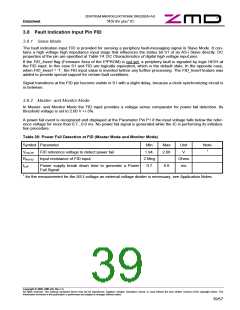
Table 26: Power Fail Detection at FID (Master Mode and Monitor Mode)
Symbol Parameter
Min
1.94.
2 Meg
0.7
Max
2.06
Unit
V
Note
1
VFID-PF FID reference voltage to detect power fail
RIN-FID
tLoff
Input resistance of FID input
Ohms
ms
Power supply break down time to generate a Power
Fail Signal
0.9
1 for the measurement for the AS-I-voltage an external voltage divider is necessary, see Application Notes.
Copyright © 2006, ZMD AG, Rev.1.4
All rights reserved. The material contained herein may not be reproduced, adapted, merged, translated, stored, or used without the prior written consent of the copyright owner. The
Information furnished in this publication is preliminary and subject to changes without notice.
39/57

 ZMD [ Zentrum Mikroelektronik Dresden AG ]