eZ80L92 MCU
Product Specification
105
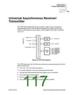
UART Functional Description
The UART function implements the following:
•
•
•
The transmitter and associated control logic.
The receiver and associated control logic.
The modem interface and associated logic.
UART Transmitter
The transmitter block controls the data transmitted on the TxD output. It implements the
FIFO, accessed through the UARTx_THR register, the transmit shift register, the parity
generator, and control logic for the transmitter to control parameters for the asynchronous
communication protocol.
The UARTx_THR is a Write-Only register. The processor writes the data byte to be
transmitted into this register. In the FIFO mode, up to 16 data bytes can be written via the
UARTx_THR register. The data byte from the FIFO is transferred to the transmit shift
register at the appropriate time and transmitted out on TxD output. After SYNC_RESET,
the UARTx_THR register is empty. Therefore, the Transmit Holding Register Empty
(THRE) bit (bit 5 of the UARTx_LSR register) is 1 and an interrupt is sent to the
processor (if interrupts are enabled). The processor can reset this interrupt by loading
data into the UARTx_THR register, which clears the transmitter interrupt.
The transmit shift register places the byte to be transmitted on the TxD signal serially. The
least-significant bit of the byte to be transmitted is shifted out first and the most significant
bit is shifted out last. The control logic within the block adds the asynchronous communi-
cation protocol bits to the data byte being transmitted. The transmitter block obtains the
parameters for the protocol from the bits programmed via the UARTx_LCTL register.
The TxD output is set to 1 if the transmitter is idle (it does not contain any data to be
transmitted).
The transmitter operates with the Baud Rate Generator (BRG) clock. The data bits are
placed on the TxD output one time every 16 BRG clock cycles. The transmitter block also
implements a parity generator that attaches the parity bit to the byte, if programmed.
UART Receiver
The receiver block controls the data reception from the RxD signal. The receiver block
implements a receiver shift register, receiver line error condition monitoring logic and
receiver data ready logic. It also implements the parity checker.
The UARTx_RBR is a Read-Only register of the module. The processor reads received
data from this register. The condition of the UARTx_RBR register is monitored by the
DR bit (bit 0 of the UARTx_LSR register). The DR bit is 1 when a data byte is received
and transferred to the UARTx_RBR register from the receiver shift register. The DR bit
PS013015-0316
Universal Asynchronous Receiver/Transmitter

 ZILOG [ ZILOG, INC. ]