P
R
E
L
I
M
I
N
A
R
Y
I
N
F
O
R
M
A
T
I
O
N
XpressFlow-2020 Series –
Ethernet Switch Chipset
SC220
XpressFlow Engine
2.3 Management Bus Interface
t Supports various industry standard micro-
t Provides separate Address and Data bus
t Supports Big & Little Endian byte ordering
t Supports 16- or 32-bit Data Bus
processors including:
à Intel 186/486 family or equivalent
à Motorola MPC series embedded processors
t Easily adapts to other industry standard CPUs
t Provides a single interrupt signal to Switch
Manager CPU
2.3.1 Pin Description
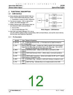
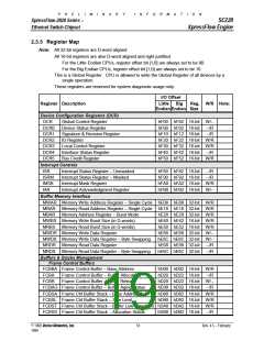
Symbol
P_C[4:0]
Type
Name & Functions
CMOS Input Processor Configuration bit [4:0]: – During the Reset Cycle, the P_C[4:0] pins provides the proc-
essor configuration. By using external weak pull-up or -down resistors, they define the External
Management Bus Interface Configuration. These inputs are sampled at the trailing edge of the
Reset cycle.
C[0] – Defines the CPU Clock input is 1X or 2X clock
C[1] – Selects either Big or Little Endian byte ordering
C[2] – Defines the polarity of the P_RWC (Rd/Wr Control) input
C[3] – Defines the CPU Data Bus width – 16-bit or 32-bit
C[4] – Defines the timing relationship between P_RDY and P_D[15:0] valid. If C[4] is High,
the P_D[15:0] are valid along in the same clock period as P_RDY is asserted. If C[4]
is Low, the P_RDY is asserted one clock period early ahead of the P_D[15:0] are
valid.
C[0]
C[1]
C[2]
C[3]
C[4]
CPU Clock
Byte Order
RWC
Bus Width
RDY Timing
Lo
Hi
1X Clock
2x Clock
Little Endian
Big Endian
P_R/W#
P_W/R#
16-bit
32-bit
Normal
Early
After RESET, these pins are used as XpressFlow Bus Data bit [31:27].
Address Bus Bit [11:1] – I/O port address
P_A[11:1]
P_D[15:0]
P_ADS#
P_RWC
TTL In
(5VT)
TTL I/O-TS Data Bus Bit [15:0] – a 16-bit synchronous data bus.
(5VT)
TTL In
(5VT)
Address Strobe – indicates valid address is on the bus
TTL
put (5VT)
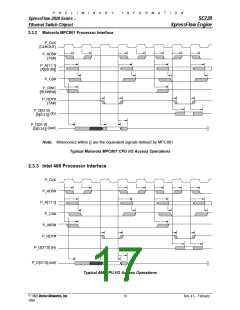
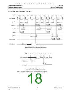
In- Read/Write Control – indicates the current bus cycle is a read or write cycle. C[1] defines the
polarity of this signal during the Reset cycle.
C[1]=Low
C[1]=High
P_R/W# is used for PowerPC or other similar processors.
P_W/R# is used for 386, 486 or other similar processors
P_RDY#
TTL Out- Data Ready – timing indicates for bus data valid
OD
P_BS16#
P_CS#
TTL Out-OD Bus Size 16 – response to bus master that the SC-201 only supports 16-bit data bus width.
TTL In
(5VT)
Chip Select – indicates the XpressFlow Engine is the target for the current bus operation.
TTL Out- Interrupt Request to Switch Manager CPU The polarity of this signal output is programmable via
P_INT
•
put
chip configuration register.
P_RSTIN#
TTL In-ST Power Up Reset Input – Asynchronous Reset Input from either Power-Up Reset circuit or from
(5VT)
Switch Manager CPU (except 386)
P_RSTOUT
P_CLK
CMOS
Output
Synchronous Reset Output – Synchronous Reset Output for i386 family as the Switch Manager
CPU
TTL In
(5VT)
CPU Clock – 1X Clock for the others
Note:
•
Output signal with programmable polarity.
15
© 1998 Vertex Networks, Inc.
Rev. 4.5 – February
1999

 ZARLINK [ ZARLINK SEMICONDUCTOR INC ]