P
R
E
L
I
M
I
N
A
R
Y
I
N
F
O
R
M
A
T
I
O
N
XpressFlow-2020 Series –
Ethernet Switch Chipset
SC220
XpressFlow Engine
2
FUNCTIONAL DESCRIPTION
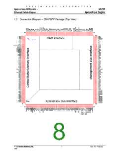
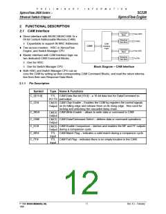
2.1 CAM Interface
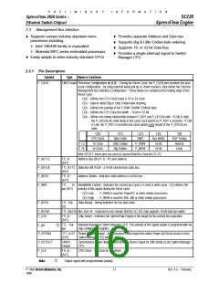
Command
From HISC
Block
t Direct interface with MUSIC MU9C1480 1k x
64 bit Content Addressable Memory (CAM)
Response
To HISC
Data Block
à Expandable to support 8k MAC Addresses
CAM
Interface
Logic
CAM
t Two access masters: HISC in XpressFlow
Command
From CPU
Block
Engine, and Switch Manager CPU
t Master interface with CAM Interface logic via
Response
To CPU
two dedicated CAM Command Blocks
Data Block
à One for HISC
à One for Switch Manager CPU
Block Diagram – CAM Interface
t Both HISC and Switch Manager CPU can ac-
cess the CAM by setting up their corresponding CAM Command Blocks, and read the return informa-
tion from their own Response Data Block
2.1.1 Pin Description
Symbol
Type Name & Functions
C_D[15:0]
TTL CAM Data Bus bit [15:0] – a 16-bit data bus for Data/Command in-
I/O-TS
put/output.
C_CE#
CAM Chip Enable – Enables the CAM by registers the control signals
on its falling edge and release them on its rising edge. Also used for
locking and unlocking the cascaded daisy chain.
CMOS
Output
C_WE#
C_CM#
C_EC#
CAM Write Enable – allows to write data or command to CAM
CMOS
Output
CAM Data/Command Select – defines data or command operations
CMOS
Output
CAM Enable Comparison – latches and enables the MF and FF outputs
during a comparison cycle.
CMOS
Output
C_MF#
C_FF#
TTL CAM Match Flag – indicates a valid match during a comparison cycle.
Input
TTL CAM Full Flag – indicates there is no empty location in the CAM.
Input
© 1998 Vertex Networks, Inc.
11
Rev. 4.5 – February
1999

 ZARLINK [ ZARLINK SEMICONDUCTOR INC ]