MVTX2801
Data Sheet
2
CPU
Addr
(Hex)
I C
Register
Description
R/W
Default
Notes
Addr
(Hex)
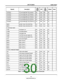
BSTRRB0
BSTRRB1
BSTRRB2
BSTRRB3
BSTRRB4
BSTRRB5
DA
BOOT STRAP read back register 0
BOOT STRAP read back register 1
BOOT STRAP read back register 2
BOOT STRAP read back register 3
BOOT STRAP read back register 4
BOOT STRAP read back register 5
DA Register
F0B
RO
RO
RO
RO
RO
RO
RO
N/A
F0C
F0D
F0E
F0F
F10
FFF
N/A
N/A
N/A
N/A
N/A
N/A
da
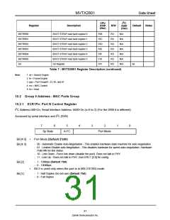
Table 7 - MVTX2801 Register Description (continued)
Note:
1. se = Search Engine
2. fe = Frame Engine
3. pgs = Port Group01, 23, 45, and 67
4. mc = MAC Control
5. tm = timer
10.2 Group 0 Address - MAC Ports Group
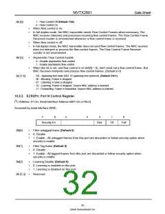
10.2.1 ECR1Pn: Port N Control Register
2
I C Address h00+2n; Serial Interface Address: h000+2n (n=0 to 3) (For the 2600 it is different)
2
Accessed by serial interface and I C (R/W)
7
6
5
4
3
2
1
0
Sp State
A-FC
Port Mode
Bit [4:0]
Bit [4:3]
•
•
Port Mode (Default 2'b00)
- 00 - Automatic Enable Auto-Negotiation - This enables hardware state machine for auto-negotiation.
- 01 - Limited Disable auto-Negotiation - This disables hardware for speed auto-negotiation. Hardware
Polls MII for link status.
- 10 - Link Down - Force link down (disable the port). Does not talk to PHY.
- 11 - Link Up - Does not talk to PHY. User ERC1 [2:0] for config.
- 1 - 10Mbps (Default 1'b0)
- 0 - 100Mbps
Bit 2 is used only when the port is in MII (10/100) mode.
Bit [2]
Bit [1]
- 1 - Half Duplex (Do not use) (Default 1'b0)
- 0 - Full Duplex
31
Zarlink Semiconductor Inc.

 ZARLINK [ ZARLINK SEMICONDUCTOR INC ]