MVTX2801
Data Sheet
This register indicates the legal egress ports. Example: A “1” on bit 3 means that packets arriving on port 0 can be
sent to port 3. A “0” on bit 3 means that any packet destined to port 3 will be discarded.
Bit[3:0]:
•
VLAN Mask for ports 3 to 0 (Default F)
- 0 - Disable
- 1 - Enable
Bit[7:4]:
•
Reserve (Default F)
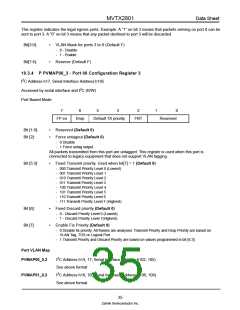
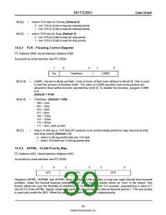
10.3.4 P PVMAP00_3 - Port 00 Configuration Register 3
2
I C Address h17, Serial Interface Address:h105
2
Accessed by serial interface and I C (R/W)
Port Based Mode
7
6
5
3
2
1
0
FP en
Drop
Default TX priority
FNT
Reserved
Bit [1:0]:
Bit [2]:
•
•
Reserved (Default 0)
Force untagout (Default 0)
- 0 Disable
- 1 Force untag output
All packets transmitted from this port are untagged. This register is used when this port is
connected to legacy equipment that does not support VLAN tagging.
Bit [5:3]:
•
Fixed Transmit priority. Used when bit[7] = 1 (Default 0)
- 000 Transmit Priority Level 0 (Lowest)
- 001 Transmit Priority Level 1
- 010 Transmit Priority Level 2
- 011 Transmit Priority Level 3
- 100 Transmit Priority Level 4
- 101 Transmit Priority Level 5
- 110 Transmit Priority Level 6
- 111 Transmit Priority Level 7 (Highest)
Bit [6]:
Bit [7]:
•
•
Fixed Discard priority (Default 0)
- 0 - Discard Priority Level 0 (Lowest)
- 1 - Discard Priority Level 7(Highest)
Enable Fix Priority (Default 0)
- 0 Disable fix priority. All frames are analysed. Transmit Priority and Drop Priority are based on
VLAN Tag, TOS or Logical Port.
- 1 Transmit Priority and Discard Priority are based on values programmed in bit [6:3]
Port VLAN Map
PVMAP00_0,3
2
I C Address h14, 17; Serial Interface Address:h102, 105)
See above format
2
PVMAP01_0,3
I C Address h18, 1B; Serial Interface Address:h106, 109)
See above format
35
Zarlink Semiconductor Inc.

 ZARLINK [ ZARLINK SEMICONDUCTOR INC ]