MVTX2801
Data Sheet
Bits [3:0]
Bits [7:4]
Signal polarity:
0: do not invert polarity (high true)
1: invert polarity
Signal select:
0: do not select
1: select the corresponding bit
For j = 2, 3, ..., 5, the value of LED_BYTEOUT_[j] equals the logical AND of all selected bits. For j = 6, the value is
equal to the logical OR. Therefore, the programmable LEDSIG[5:2] registers allow any conjunctive formula including
any of the 4 status bits (COL, FDX, SP1, SP0) or their negations to be sent to the LED_BYTEOUT_[5:2] pins.
Similarly, the programmable LEDSIG[6] register allows any disjunctive formula including any of the 4 status bits or
their negations to be sent to pin LED_BYTEOUT_[6].
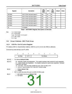
LEDSIG[7] is used for programming both LED_BYTEOUT_[1] and LED_BYTEOUT_[0]. As we will see, it has other
functions as well. The format is as follows:
7
4
3
0
GP
RxD
TxD
FC
P6
RxD
TxD
FC
Bits [7]
•
•
Global output polarity: this bit controls the output polarity of all LED_BYTEOUT_ and
LED_PORT_SEL pins. (Default 0)
- 0: do not invert polarity (LED_BYTEOUT_[7:0] are high activated; LED_PORT_SEL[9:0] are low
activated)
- 1: invert polarity (LED_BYTEOUT_[7:0] are low activated; LED_PORT_SEL[9:0] are high activated)
Bits [6:4]
Bit [3]
Signal select:
- 0: do not select
- 1: select the corresponding bit
•
•
The value of LED_BYTEOUT_[1] equals the logical OR of all selected bits. (Default 110)
Polarity control of LED_BYTEOUT_[6]
(Default 0)
- 0: do not invert
- 1: invert
Bits [2:0]
•
•
Signal select:
- 0: do not select
- 1: select the corresponding bit
The value of LED_BYTEOUT_[0] equals the logical OR of all selected bits. (Default 001)
27
Zarlink Semiconductor Inc.

 ZARLINK [ ZARLINK SEMICONDUCTOR INC ]