MT88L70
Data Sheet
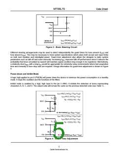
the steering time constants externally, allows the designer to tailor performance to meet a wide variety of system
requirements.
Digit
TOE
INH
ESt
Q4
Q3
Q2
Q1
ANY
1
L
X
X
X
X
X
X
X
X
X
X
X
X
X
L
H
H
H
H
H
H
H
H
H
H
H
H
H
H
H
H
H
L
Z
0
0
0
0
0
0
0
1
1
1
1
1
1
1
1
0
Z
0
0
0
1
1
1
1
0
0
0
0
1
1
1
1
0
Z
0
1
1
0
0
1
1
0
0
1
1
0
0
1
1
0
Z
1
0
1
0
1
0
1
0
1
0
1
0
1
0
1
0
H
H
H
H
H
H
H
H
H
H
H
H
H
H
H
H
H
H
H
H
2
3
4
5
6
7
8
9
0
*
#
A
B
C
D
A
B
C
D
L
L
L
H
H
H
H
undetected, the output code
will remain the same as the
previous detected code
L
L
L
Table 1 - Functional Decode Table
L=LOGIC LOW, H=LOGIC HIGH, Z=HIGH IMPEDANCE
X = DON‘T CARE
Guard Time Adjustment
In many situations not requiring selection of tone duration and interdigital pause, the simple steering circuit shown
in Figure 3 is applicable. Component values are chosen according to the formula:
tREC=tDP+tGTP
tID=tDA+tGTA
The value of tDP is a device parameter (see Figure 7) and tREC is the minimum signal duration to be recognized by
the receiver. A value for C of 0.1 µF is recommended for most applications, leaving R to be selected by the
designer.
4
Zarlink Semiconductor Inc.

 ZARLINK [ ZARLINK SEMICONDUCTOR INC ]