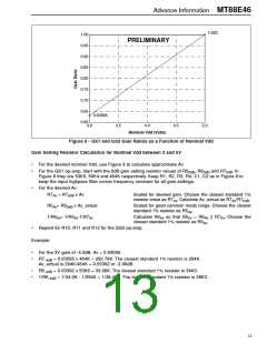
MT88E46 Advance Information
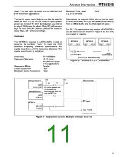
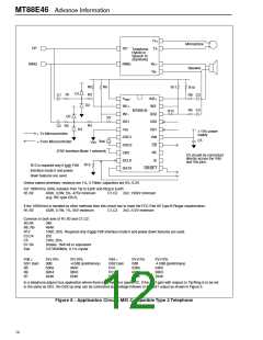
Tx+
Tx-
Microphone
Speaker
TIP
TIP
Telephone
Hybrid or
Speech IC
(Symbolic)
RING
RING
Rx+
Rx-
R5
R3
R6
R11
R10
D1
R1
D3
C1
R8 C3
V
IN2+
IN2-
GS2
CB2
CB1
Vdd
CD
REF
D2
IN1+
IN1-
R9 C4
MT88E46
R12
R7
GS1
R4
C2 R2
= To Microcontroller
= From Microcontroller
D4
Vss
10% power
supply
OSC1
OSC2
CB0
C5
Xtal
Vss
(FSK Interface Mode 1 selected)
NC
C5 should be connected
directly across the Vdd
and Vss pins.
DCLK
DATA
IC
R13
R13 is required only if both FSK
interface mode 0 and power
down features are used.
DR/DET
Unless stated otherwise, resistors are 1%, 0.1Watt; capacitors are 5%, 6.3V.
For 1000Vrms, 60Hz isolation from Tip to Earth and Ring to Earth:
R1,R2
430K, 0.5W, 5%, 475V minimum
(e.g. IRC type GS-3)
C1,C2
2n2, 1332V minimum
If the 1000Vrms is handled by other methods then this circuit has to meet the FCC Part 68 Type B Ringer requirements:
R1,R2 432K, 0.1W, 1%, 56V minimum C1,C2 2n2, 212V minimum
Common to both sets of R1,R2 and C1,C2:
R3,R4
R8, R9
R13
34K
464K
100K, 20%. Required only if both FSK interface mode 0 and power down features are used.
C3,C4
C5
2n2
100n, 20%
D1-D4
Xtal
Diodes. 1N4148 or equivalent
3.579545MHz, 0.1% crystal
Vdd =
GS1 Gain
R5
R6
R7
5V 10%
0dB
53K6
60K4
464K
3V 10%
-4.0dB (preliminary)
34K0
38K3
294K
Vdd =
GS2 Gain
R10
R11
R12
5V 10%
0dB
53K6
60K4
464K
3V 10%
-4.0dB (preliminary)
34K0
38K3
294K
In a telephone adjunct box application where there is no hybrid or speech IC, if the GS2 gain with respect to Tip/Ring is to be set
to the same as GS1, the GS2 op-amp can be connected as a voltage follower to the GS1 output as shown in Figure 5.
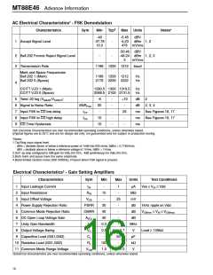
Figure 8 - Application Circuit: MEI Compatible Type 2 Telephone
12

 ZARLINK [ ZARLINK SEMICONDUCTOR INC ]